LightWare GRF250 / GRF500
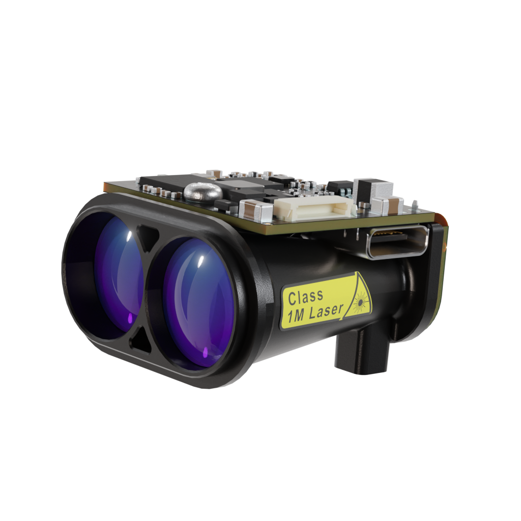
The LightWare GRF250 and GRF500 are long-range lidar-based rangefinders. Both models support serial (UART) and I2C communication and provide accurate distance and signal-strength data at configurable update rates.
GRF250: 0.2 m – 250 m range
GRF500: 0.2 m – 500 m range
Note
Support for the LightWare GRF250 and GRF500 sensors via UART/I2C was added in ArduPilot 4.7.
Serial (UART) Connection
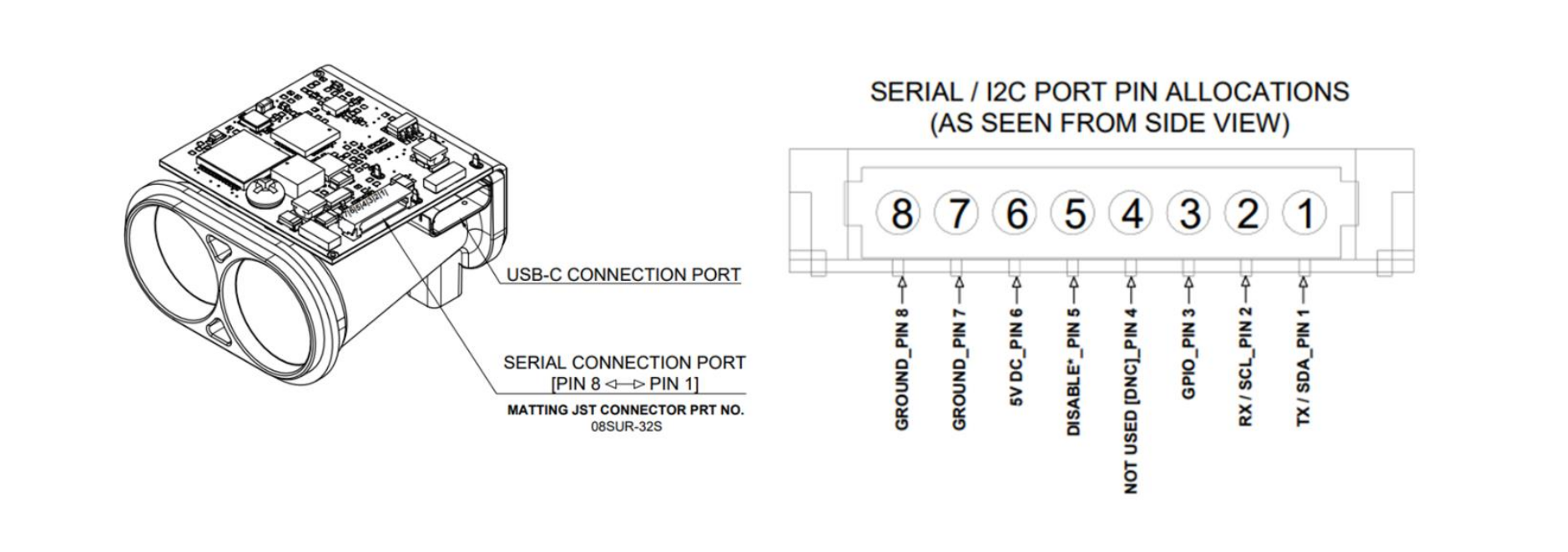
The GRF sensors communicate via UART using 3.3 V or 5 V logic levels. Connect the TX of the Lidar to the RX of the autopilot UART port, and the RX of the Lidar to the TX of the same port. Also connect GND and 5 V to power the sensor.
Example (SERIAL4):
If the GRF is connected to the autopilots’ SERIAL4 port and it is the first rangefinder:
SERIAL4_PROTOCOL = 9 (Lidar)
SERIAL4_BAUD = 115 (115200 baud)
RNGFND1_TYPE = 45 (LightWareGRF)
RNGFND1_SCALING = 1
RNGFND1_MIN = 0.2
RNGFND1_MAX = 250 (for GRF250) or 500 (for GRF500)
If instead you are using the SERIAL2 port, set SERIAL2_PROTOCOL = 9 and SERIAL2_BAUD = 115.
Power note: The GRF sensors can draw higher current than typical serial peripherals. Check your flight controller’s 5 V peripheral rail limits — an external 5 V supply may be required.
I2C Connection
The GRF250 and GRF500 also expose an I2C interface. Connect the sensor’s SDA and SCL lines to any spare I2C bus on the autopilot, along with GND and 5 V. The same power-rail consideration described above applies — use an external 5 V supply if the autopilot’s peripheral rail cannot supply the sensor’s peak current.
The sensor’s default 7-bit I2C address is 0x66 (decimal 102).
Set the following parameters, then reboot the autopilot:
RNGFND1_TYPE = 48 (LightWare-GRF-I2C)
RNGFND1_ADDR = 0 (leave at the default; the driver then probes the sensor’s factory address of 102 decimal / 0x66. Only set this to a non-zero I2C address to force a specific one, for example when running a second I2C rangefinder on the same bus or if you have reprogrammed the sensor to a non-default address)
RNGFND1_MIN = 0.2
RNGFND1_MAX = 250 (for GRF250) or 500 (for GRF500)
No SERIALx_PROTOCOL setup is required when using the I2C interface. The driver auto-detects the sensor on every probed I2C bus, so the device can be plugged into any available I2C port. On a successful boot, the autopilot will send a GCS message of the form LightWare GRFxxx detected (I2C).
Additional GRF-specific Parameters
The GRF-specific parameters below apply to both the serial (TYPE = 45) and I2C (TYPE = 48) backends.
When RNGFNDx_TYPE is set to a LightWare GRF backend and the autopilot is rebooted, the following additional parameters become available:
RNGFNDx_GRF_RET: Selects which return type to use (0: FirstRaw, 1: FirstFiltered, 2: LastRaw, 3: LastFiltered).
RNGFNDx_GRF_ST: Sets the minimum acceptable return signal strength in dB. Returns weaker than this value are ignored (0 disables filtering).
RNGFNDx_GRF_RATE: Sets the sensor update rate in Hz. GRF250 supports 1–50 readings per second, while GRF500 supports 0.5–10 readings per second.
Testing the Sensor
You can view the live distance readings in Mission Planner → Flight Data → Status tab, under the field named “rangefinder1” (or rangefinder2 / 3 for additional sensors).
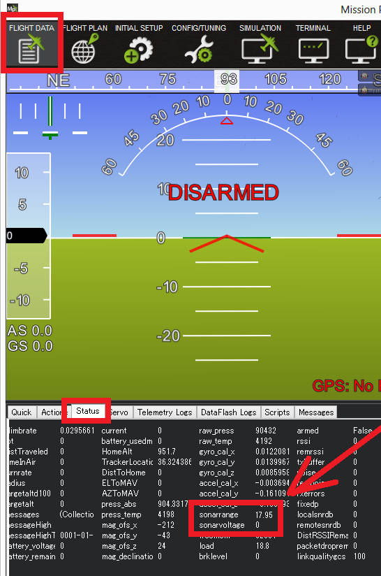
If values remain at zero, verify wiring and power supply. For serial connections, also confirm the baud rate and protocol; for I2C connections, confirm the bus wiring, and if you have set RNGFND1_ADDR to force an address, that it matches the sensor’s actual address.