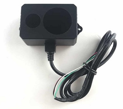
Benewake TF02-Pro / TF03 / TFS20-L / TF-Luna / TF-Nova / TF350
Benewake provides a range of lidar sensors that use proprietary serial, I2C and/or CAN interfaces
Model |
Range (Min/Max) |
Weight |
Voltage |
FOV |
Interface |
|---|---|---|---|---|---|
TF02 (discontinued) |
0.22m / 10m |
52g |
5V |
3 deg |
UART, I2C |
0.40m / 13.5m |
50g |
5V~12V |
3 deg |
UART, I2C |
|
0.40m / 13.5m |
60g |
7V~30V |
3 deg |
CAN, I2C |
|
1m / 50m |
89g |
5V~24V |
0.5 deg |
UART, CAN |
|
0.20m / 15m |
2g |
3.3V |
2 deg |
UART, I2C |
|
0.20m / 8m |
5g |
3.7V~5.2V |
2 deg |
UART, I2C |
|
0.14m / 7m |
5g |
5V |
14 deg |
UART, I2C |
|
3.5m / 150m |
224g |
5V~24V |
0.35 deg |
UART, CAN |
More details on these lidar can be found in the benewake.com’s downloads section
Where to Buy
Connecting via Serial
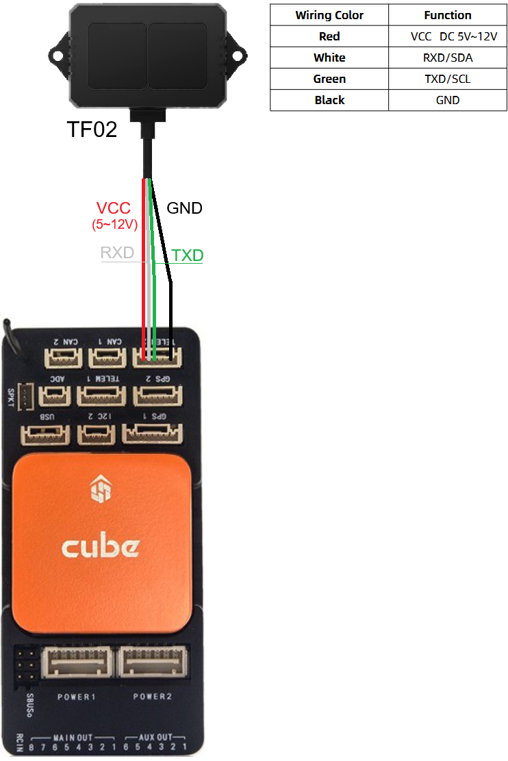
For a serial connection you can use any spare Serial/UART port. The diagram below shows how to connect a TF02 to Serial2. Please note that wire colours may vary by model so please check the datasheet.
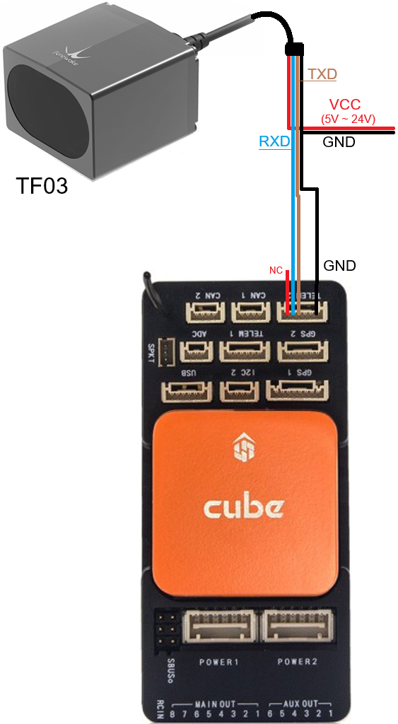
The diagram below shows how to connect a TF03 to Serial2
The diagram below shows how to connect a TF-Nova to Serial2
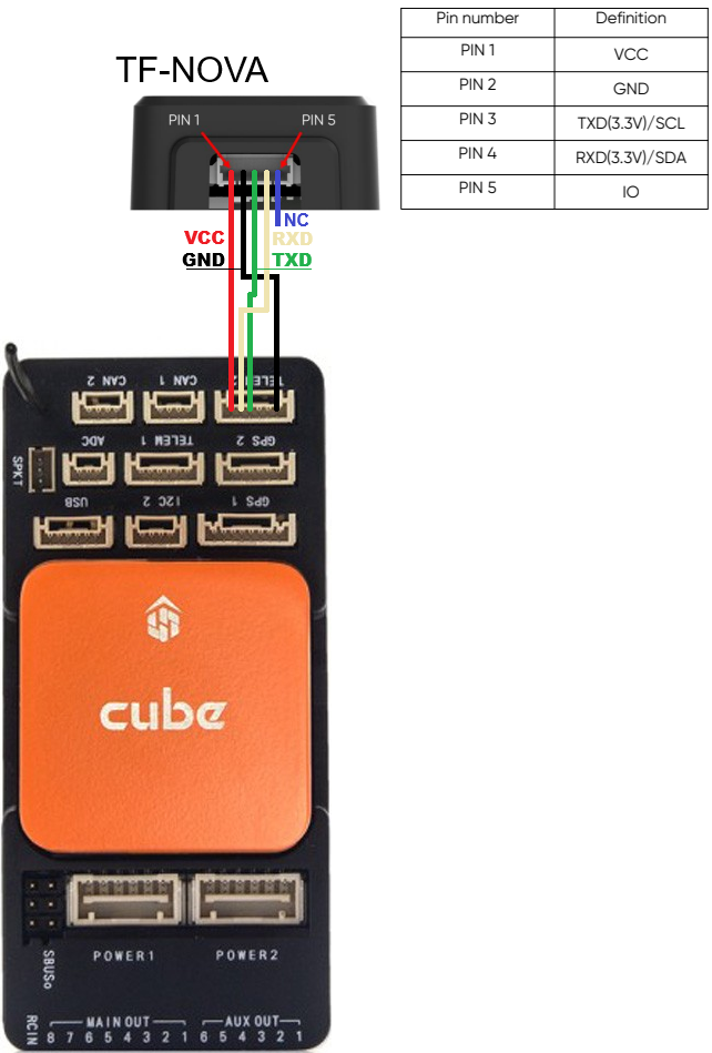
If SERIAL2 is being used, then use the following parameters to set the first rangefinder:
SERIAL2_PROTOCOL = 9 (Lidar)
SERIAL2_BAUD = 115 (115200 baud)
RNGFND1_TYPE = 19 (BenewakeTF02) for TF02, 27 (BenewakeTF03) for TF02-Pro, TF03, TFS20-L, TF-Luna, TF-Nova, TF350.
RNGFND1_MIN = Use a distance the rangefinder could reliably read in [metres]. For TF02: 0.22, for TF03: 1, or look up the top table of this page for other sensors.
RNGFND1_MAX = Use a distance the rangefinder could reliably read in [metres]. For TF02: 10, for TF03: 50, or look up the top table of this page for other sensors.
RNGFND1_ORIENT = 25 (Down) Indicates the position the rangefinder is set to read.
RNGFND1_GNDCLR = 0.1 An accurate distance in [metres] from the rangefinder to the ground when the vehicle is landed. This value depends on how you have mounted the rangefinder.
Connecting via I2C
All of these lidar except the TF03 and TF350 can also be connected to the autopilot’s I2C port. The sensor may need to be switched from its default output mode to I2C first - see the relevant Benewake datasheet.
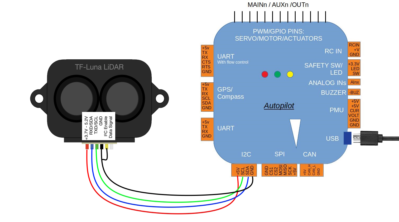
For the TFS20-L, which has its own driver, set:
RNGFND1_TYPE = 46 (BenewakeTFS20L-I2C)
For the other I2C capable models set:
RNGFND1_TYPE = 25 (BenewakeTFmini-I2C). These sensors share the TFmini Plus I2C command protocol, so this one driver serves them all.
Then in either case set:
RNGFND1_ADDR = 16 (I2C address of the lidar in decimal, equivalent to 0x10 hexadecimal, which is the default for these sensors)
RNGFND1_MIN = Use a distance the rangefinder could reliably read in [metres]. Look up the top table of this page for your sensor.
RNGFND1_MAX = Use a distance the rangefinder could reliably read in [metres]. Look up the top table of this page for your sensor.
RNGFND1_ORIENT = 25 (Down) Indicates the position the rangefinder is set to read.
RNGFND1_GNDCLR = 0.1 An accurate distance in [metres] from the rangefinder to the ground when the vehicle is landed. This value depends on how you have mounted the rangefinder.
Note
The RNGFND1_PIN, RNGFND1_RMETRIC, RNGFND1_SCALING and RNGFND1_STOP_PIN parameters only apply to analog rangefinders and have no effect on an I2C connection.
Connecting via CAN
The TF02-i, TF03, TFmini-i and TF350 can be connected to the autopilot via CAN. The diagram below shows how to connect a TF03 to CAN1. Please note that wire colours may vary by model so please check the datasheet.
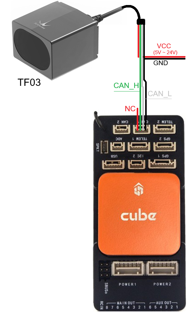
If CAN1 is used then set the following parameters:
CAN_P1_DRIVER = 1 (First driver)
CAN_D1_PROTOCOL = 11 (Benewake)
RNGFND1_TYPE = 34 (Benewake_CAN)
RNGFND1_MIN = Use a distance the rangefinder could reliably read in [metres]. For TF02-i: 0.4, for TF03: 1, or look up the top table of this page for other sensors.
RNGFND1_MAX = Use a distance the rangefinder could reliably read in [metres]. For TF02-i: 13.5, for TF03: 50, or look up the top table of this page for other sensors.
RNGFND1_ORIENT = 25 (Down) Indicates the position the rangefinder is set to read.
RNGFND1_GNDCLR = 0.1 An accurate distance in [metres] from the rangefinder to the ground when the vehicle is landed. This value depends on how you have mounted the rangefinder.
Note
Check the information at Sensor Position Offset Compensation in order to configure the position where the range finder is installed.
Testing the sensor
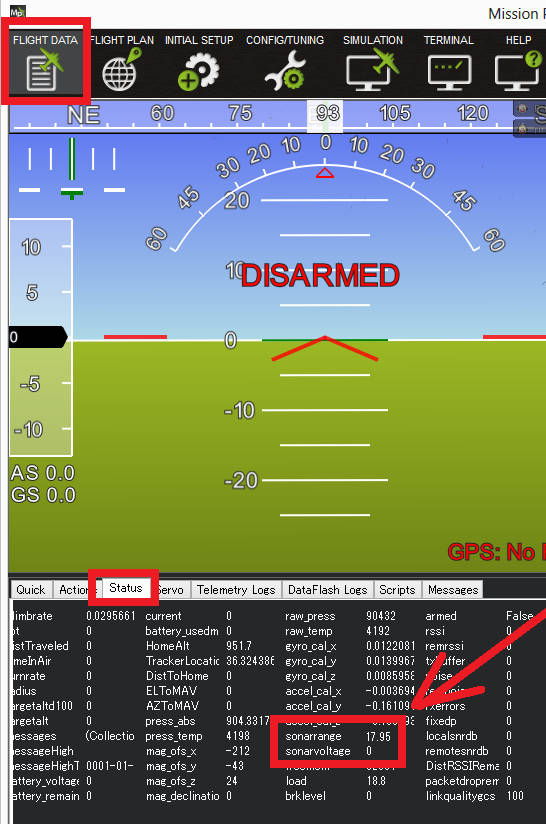
Distances read by the sensor can be seen in the Mission Planner’s Flight Data screen’s Status tab. Look closely for “rangefinder1”.