Rpanion Server Installation
This page explains how to install Rpanion Server on an RPI compute module connected to an autopilot. Rpanion Server’s official installation instructions can be found here
Recommended Hardware
(optionally) CSI/MIPI camera
Ochin Ethernet Solder Bridge (Optional)
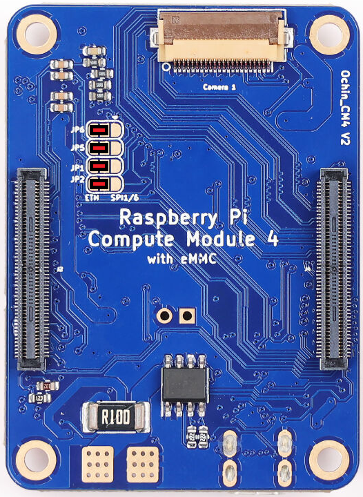
As mentioned here in the Ochin wiki, four solder bridges as shown in red below are required to enable Ethernet support for the RPI.
Installing Rpanion Server on RPI4 or RPI5
Install rpiboot and rpi-imager on your Ubuntu or Windows PC
Ubuntu users should run
sudo apt install rpiboot
sudo apt install rpi-imager
Windows user instructions are here but in short you should:
On the RPI I/O board
Mount the RPI CM4/CM5 on the RPI I/O board
Add jumper so the RPI CM starts in bootloader mode, “Fit jumper to disable eMMC Boot”
Connect I/O board to PC via USB
Power on the I/O board (if using the RPI5 I/O board this step is probably done by the above step)
On your PC
Open a web browser to the Rpanion Server release page, under “Disk images” find and download the appropriate image for your RPI model
run rpiboot:
Ubuntu users should open a terminal and enter “rpiboot”
Windows users should open the start menu and run “rpiboot-CM4-CM5 Mass Storage Gadget”
run rpi-imager:
Ubuntu users should open a terminal and enter “rpi-imager”
Windows users should open from start menu run “Raspberry Pi Imager”
from within RPI Imager:
Choose Device: “Raspberry Pi 4” or “Raspberry Pi 5”
Operating System: Use custom, select downloaded .img file
Storage: select RPI drive (should have appeared after rpiboot was run)
Select “No” when asked to apply special settings
Configuring the Connection to the Autopilot
After the above installation is complete, perform the initial setup of Rpanion Server
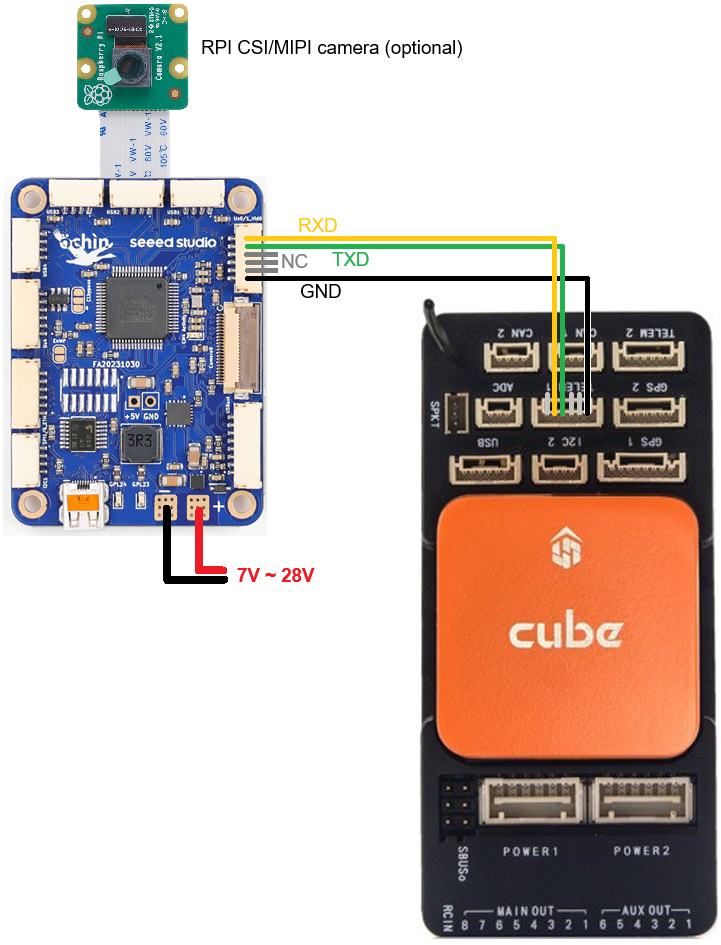
Install the RPI on the Ochin Carrier Board connected to one of the autopilot’s serial ports as shown in the image at the top of this page
Make sure a WiFi antenna is attached to the RPI
Connect to Rpanion Server via Wifi
Wait for the “rpanion” wifi access point to appear and connect (password is “rpanion123”)
Disable BlueTooth which may interfere with the RPI’s serial ports
Use Putty (or any similar terminal program) to connect to the RPI using SSH
Host Name: 10.0.2.100
Connection Type: SSH
Port: 22
Username/password: pi/raspberry
Open /boot/firmware/config.txt with your favourite linux text editor:
sudo nano /boot/firmware/config.txt
sudo vi /boot/firmware/config.txt
Add “dtoverlay=disable-bt” to the end of the file as shown below
[all]
enable_uart=1
dtoverlay=disable-bt
Save and exit the text editor and reboot the RPI
Open a browser to http://10.0.2.100:3001/ and enter username: admin, pw: admin
Select “Flight Controller” from the left menu
Input Type: UART
Serial Device: /dev/serial0 (or whatever option appears in the drop-down)
Baud Rate: 921600
MAVLink Version: 2.0
Push the “Start Telemetry” button but note that no packets will be received until the autopilot is configured as described below
Connect the autopilot to your PC with a USB cable and then connect with any GCS (e.g. Mission Planner, QGC) and set the following parameters. Please note these assume Serial1 (aka Telem1) is physicall connected to the RPI:
SERIAL1_BAUD = 921 (921600 bps)
SERIAL1_PROTOCOL = 2 (MAVLink2)
(Optionally) BRD_SER1_RTSCTS = 0 (Disable clear-to-send/ready-to-send)
Reboot the autopilot and check on Rpanion’s Flight Controller screen that mavlink packets are being received
Confirm the ground station can connect to the autopilot through Rpanion’s Wifi AP
If using Mission Planner
From the top-right of the screen select, “UDPCl” and press connect
Enter host name/ip: 10.0.2.100
Enter remote port: 14550
Press Connect