Archived:Rover PX4FMU/PX4IO Wiring and Quick Start
Warning
ARCHIVED
The PX4 is end of life and is not generally available for purchase. This article is made available for existing users.
This article provides high level information about how to wire up the PX4FMU/PX4IO autopilot board for Rover and connect its most important peripherals.
Mounting the PX4FMU / PX4IO board stack
It is recommended that you mount the PX4FMU / PX4IO board stack upside down with the PX4IO board on top to provide unrestricted access to the connectors on the PX4IO board. If you do mount the PX4IO board on top you will need to specify the AHRS_ORIENTATION as number 8 or roll 180 in the Mission Planner Advanced Parameter list.
See also Mounting the Flight Controller.
RC Setup
Pixhawk uses a single PPM sum RC input. Output depends on whether a steering servo or “skid steer” (left or right motors turn faster to turn in the opposite direction) is used on your rover
** PX4** |
Car |
Skid Steer |
1 |
Steering Servo |
Left Motor |
2/3 |
Motor ESC |
Right Motor |
Output Channels:
Reassigning your RC transmitter stick channels
The default transmitter stick configuration should be suitable in almost all cases. If you do need to change them, then see RCMAP Input Channel Mapping.
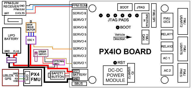
Normal One Motor Servo Steering Wiring Diagram
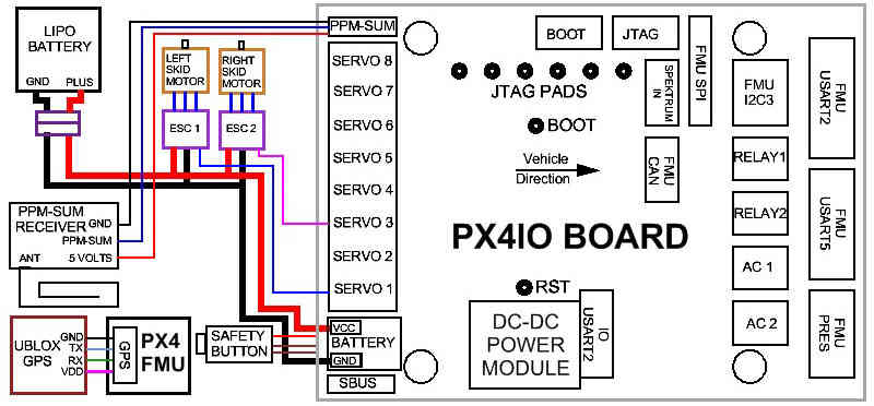
Two Motor Skid Steering Wiring Diagram
Check out the Basic Operating Modes of the Rover2 Firmware
The board must have its automatic Safety disengaged before the Rover can be driven.
Safety Button LED Indications:
Fast Blinking indicates: Error Condition, Safety cannot be disengaged. Possibly not calibrated or sensor error.
Slow Blinking indicates: Safe condition. Safety can be disengaged by depressing Safety Button for 5 seconds.
LED Continuously on indicates: Safety has been disengaged. PX4 controller may be armed with Throttle down and to the right.
When the LED is continuously on indicating Safety Disengaged it may be toggled back to a Safety engaged condition by depressing the Safety button for 5 seconds.
Both the Safety engaged and Safety disengaged conditions require the button to be held down for 5 seconds to toggle them. This is a safety mechanism to prevent accidental disarming during use and to prevent accidental arming during transportation.
Test MANUAL mode
To test the Manual mode, put the Rover up on blocks, to prevent a runaway, turn on the R/C transmitter, power up the autopilot (depressing the safety button on the PX4FMU for 5 seconds to disengage the safety lock (LED solid on)), and when a 3D lock has been obtained
verify that when the elevator joystick is moved forward that the rover goes forward and vice versa, and that when the aileron joystick is moved to the left,
the steering wheels go to the left and vice versa.
A R/C receiver radio tester that can display channel PWM values can also be used to determine the throttle and steering outputs of the Pixhawk.
If either the throttle or steering channel is reversed, then the R/C transmitter channel reversing function must be used to reverse the appropriate channel.
Test AUTO mode
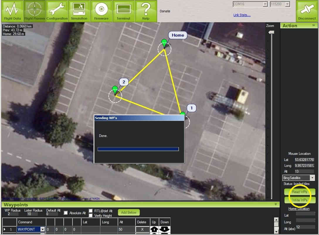
To test the Auto mode at least one waypoint that is either to the right or the left of the home waypoint must be loaded into the APM using the MP Flight Planner:
Using the same test setup as in the Manual mode, verify using the Manual mode that the Rover throttle and steering are still functional.
Then moving the mode switch to the put the Rover in the Auto mode, verify that the Rover motor comes up to a speed commensurate with the Cruise Throttle value that was previously selected and that the steering moves to either the right or the left depending on where the first waypoint was selected relative to the home waypoint. If either the throttle or the steering is reversed, the Radio Calibration in the MP Configuration Tab (not the R/C transmitter) must be used to reverse the appropriate channel by checking the appropriate “reverse” box on either the aileron (steering) or the throttle.
Once the functionality of the Manual and Auto modes has been verified, use the Flight Planner Tab in the MP to setup a waypoint course. Make sure to set the Waypoint Radius to around 2 meters for good performance.
A more complete guide to using the Mission Planner with Rover is described in Learning a Mission.