ARCHIVED: page considered obsolete
Camera Shutter Triggering using CHDK
This article explains how to set up camera shutter triggering for Canon Cameras that support the Canon Hacker Development Kit (CHDK).
Overview
ArduPilot allows you to configure a servo or relay output as the control signal for the camera shutter so that it can be used in Camera Missions. Additional hardware is required to convert the shutter activation signal to the format expected by the particular camera.
This article explains how to set up the shutter-trigger for Canon Cameras that support the Canon Hacker Development Kit (CHDK). The method connects the ArduPilot output to the camera using a *custom cable*, and causes a script running on the camera to take pictures when the relay output voltage goes high.
At the end of the article is a list of cables that you can purchase instead of using the custom cable (please extend this list if you find another appropriate cable).
The article covers both Pixhawk and APM2.x.
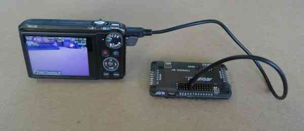
APM Connected to a Canon SX260 HS using a custom cable
Note
It is also possible to use a servo output instead of a relay.
CHKD and ArduPilot integration
CHDK is an experimental (and free) development tool, which temporarily patches (supported) Canon cameras so that they can be controlled using scripts. The scripts are able to take pictures, control the camera zoom, set the focus, and access many other camera features.
Scripts can also read the camera USB port voltage and execute different instructions/functions based on the signal pulse-length. When using a relay, the script can be very simple — all it needs to do is check the voltage (in a loop), and take a picture when it detects the relay voltage go high. More complicated scripts might first set the focus, zoom, or perform any other default behaviour.
The CHDK Wiki documentation explains which cameras are supported, how you install CHDK on you camera, and how to install and run scripts.
Cable for connecting to Pixhawk
Note
See CHDK cables for purchase if you just want to buy a cable. This section is useful if you want to create your own cable or understand what the cable needs to do.
For Pixhawk you have to modify the APM cable in the following section, adding a circuit step the output pin signal voltage from 3.3 to 5 volts. This is required because the relay/servo output voltage is approximately 3.3V while CHDK needs 5V to trigger.
A circuit and PCB you can use are shown below. 5V should be supplied from a BEC (or from a BEC powering the central pin on the AUX output rail) because the servo rail itself is not powered.
1 x BC547 or 2N3904
1 x BC557 or 2N3906
2 x 1 K
1 x 220 ohm

3Vto 5V Shifter Circuit

3V to5V Shifter (PCB)
Note
The voltage stepper circuit and PCB above are from the community discussion boards.
It is also possible to find pre-built stepper circuits like the SparkFun 5V Step-Up Breakout - NCP1402 (not tested).
Cable for connecting to APM
A cable is needed to connect the APM board to the camera USB port. This section shows how to modify the USB cable that is supplied with the camera, replacing the standard USB connector with a 3-position header that can connect to the AMP output port.
Note
This example uses the USB Mini-B connector that comes with the SX260 HS camera. The same approach should work equally well using the supplied cable on any CHDK-supported Canon Powershot camera.
The components used to attach the servo connector to the wire are shown below. If you don’t have a crimp tool you can just solder a spare servo wire connector instead.
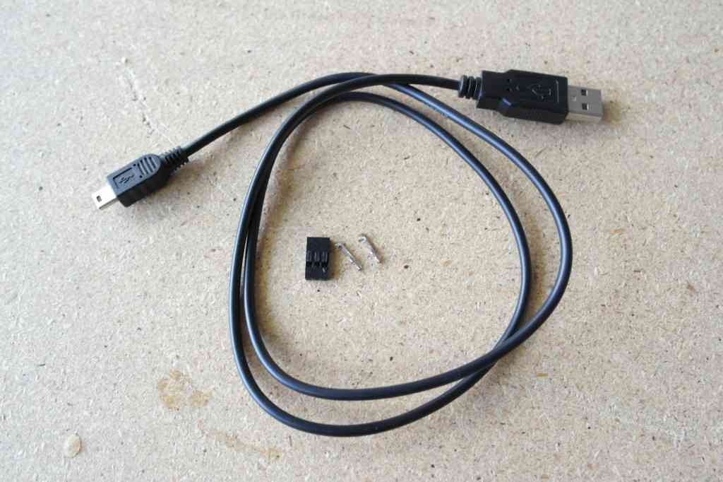
APM CHDK Camera Control Cable: Parts needed
We’ll only be using the Mini-B side of this cable, so measure whatever length you need from that end depending on how your camera and autopilot mount in your airframe. I’ve measured out about 14″ and cut the cable completely through. Inside are four wires, we only need the red and black wire so cut away the green and white wires. Strip the ends of the red and black wires.
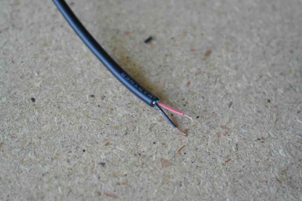
CHDK Camera Control Cable:Stripped Wires
If you have the crimp tool, crimp and insert the wires into the first and third positions of a 3-position header. If you don’t have the crimp tool, solder these two wires to the ground and signal wires of a spare servo wire. Insert the ground wire into the side with an arrow so you can tell which wire is which later on.
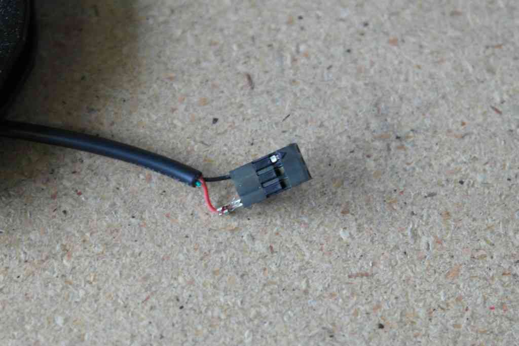
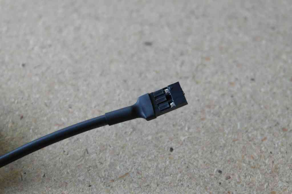
CHDK Camera Cable:Attaching the 3-Position Header
Cover the connector with heatshrink. Be careful with the hot air near the connector as it can cause the locking plastic pieces in the receptacle to deform.
ACHDK Camera Cable: Connector covered withHeatshrink
Camera shutter configuration in Mission Planner
Camera Shutter Configuration in Mission Planner explains how to configure a Pixhawk AUX output or the APM2.x A9 pin as a relay camera trigger. Connect the cable to the appropriate port as described, and to the camera.
The specific Mission Planner settings required for this CHDK hardware are listed below. Note that duration required may be different on some cameras:
Pixhawk:
CAM_TRIG_TYPE: 1 (Relay).Shutter (Port): RC10 (Name of connected port, in this example we use RC10 = AUX2).
APM2.x:
Shutter (Port): Relay (A9 Pin).
Shutter Duration: 1 (1/10 second)CH7_OPT: 9 (Optional - enables manual shutter triggering on Copter only).
The servo settings are not used for the relay configuration, and can be ignored.
Creating and installing the CHDK script
One of the simplest scripts you can use is E38_APM.bas, which simply waits on the relay signal and then takes a picture (originally from www.event38.com):
rem Event 38 APM Tie-In Script
rem Free For Modification & Distribution
@title E38_APM
print "Script Started, Listening"
sleep 1000
goto "interval"
:interval
  p = get_usb_power
  if p > 0 then goto "picture"
  goto "interval"
:picture
  press "shoot_full"
  sleep 50
  release "shoot_full"
  goto "interval"
:terminate
  print "Shut-Down Command Received"
  sleep 1000
  shut_down
Alternatively you can use a more advanced script to set up the camera focus, exposure or other settings before taking the picture. A good starting point is the open source KAP UAV Exposure Control Script (v3.1). This was used as the basis for the 3DR Aero Plane 3DR EAI (Exposure-Aperture-ISO) script described in the Aero-M Operation Manual.
The CHDK Wiki explains how you set up CHDK and install and activate scripts for your particular camera. Installing scripts is usually as simple as copying them into the “scripts” directory on your SD card. You can then activate them by navigating to the menu Miscellaneous Stuff | Remote Parameters and making sure the Enable Remote setting is checked.
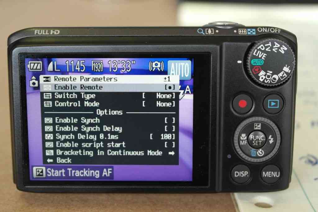
CHDK: Camera Menu to EnableRemote
Testing
Load and run your CHDK script. On Copter you should be able to trigger the shutter using the CH7 switch.
On other vehicles set the CAM_TRIGG_DIST to 1 or 2 meters. Small
changes in the GPS readings will cause the distance value to count up
slowly and it should trigger the shutter every few seconds. If nothing
happens at all, take your vehicle outside and walk around to make sure
that some distance is detected. If your camera lens closes and opens
instead of taking a picture, make sure the CHDK remote enable setting
is activated on the camera.
Using a servo instead of a relay
It is also possible to trigger the camera shutter using a servo output, but that requires additional (and often more expensive) hardware to decode the servo’s PWM signal. The CHDK Camera Control Tutorial describes a suitable PWM-to-voltage pulse cable, and information from which the servo settings can be inferred.
Note
The CHDK Camera Control Tutorial integrates with the camera as a “generic servo” rather than as a shutter trigger. This approach means that camera triggering is not as well integrated with mission planning, but more camera commands can be called.
CHDK Cables for purchase
This section is for listing CHDK cables that you can purchase (rather than creating your own, as described in this article). Please extend the list if you discover more.
Tuffwing camera trigger cable for Pixhawk
Tuffwing camera trigger cable for connecting Pixhawk to a CHDK Canon PowerShot. This includes circuitry to upscale the Pixhawk 3.3 volt signal to 5 volts from the + pin. You’ll need to have an ESC with an BEC or UBEC plugged into any of the open AUX or MAIN OUTs on the Pixhawk.
Pixhawk Camera Trigger Cable (User Guide)
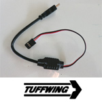
Tuffwing Pixhawk CHDK Camera Trigger Cable