Sonar Sensors
ARCHIVED
Sonar sensors can provide obstacle avoidance functionality for Rover. This page provides instructions for installing, configuring, and testing single and double sonar setups.
Note
This article is out of date. Sonars are now more generically
represented by “Rangefinders” - Rover can support 4. The relevant
parameters have morphed from “SONAR” to “RNGFND” . See the RNGFNDx_y parameters, such as RNGFND1_TYPE.
What you’ll need
Sonar (ultrasonic) sensors allow Rover to detect obstacles and avoid them. Sonar sensors can be more sensitive than IR sensors, making them the preferred option for obstacle avoidance. Normally, a single sonar sensor is used, at the front of the rover. But Rover also supports the use of two sonar sensors, one pointing a bit to the right and the other a bit to the left, to not only detect obstacles but steer away from them.
To implement sonar sensors, you will need:
One or two Maxbotics MB1240 XL Maxsonar EZ4 sensors.
A servo extension cable with female connector on one end to connect each sensor (or cut one end off a female-female servo cable).
Connect the sensor
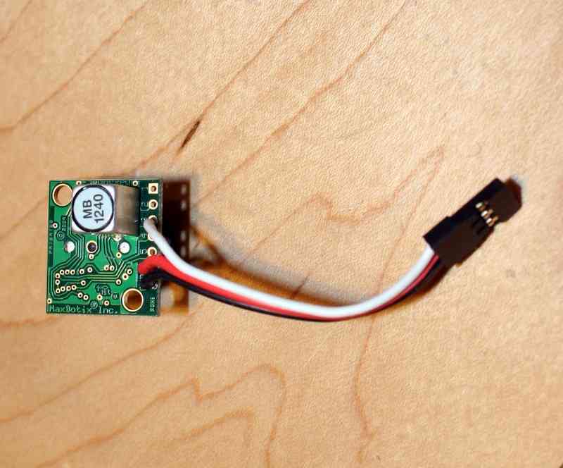
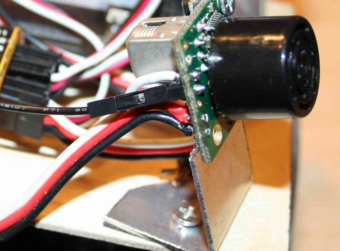
Solder the servo cable wires to the sensor’s GND (black wire), V+ (red wire) and “3” (white wire) holes as shown below. Click on images to enlarge.
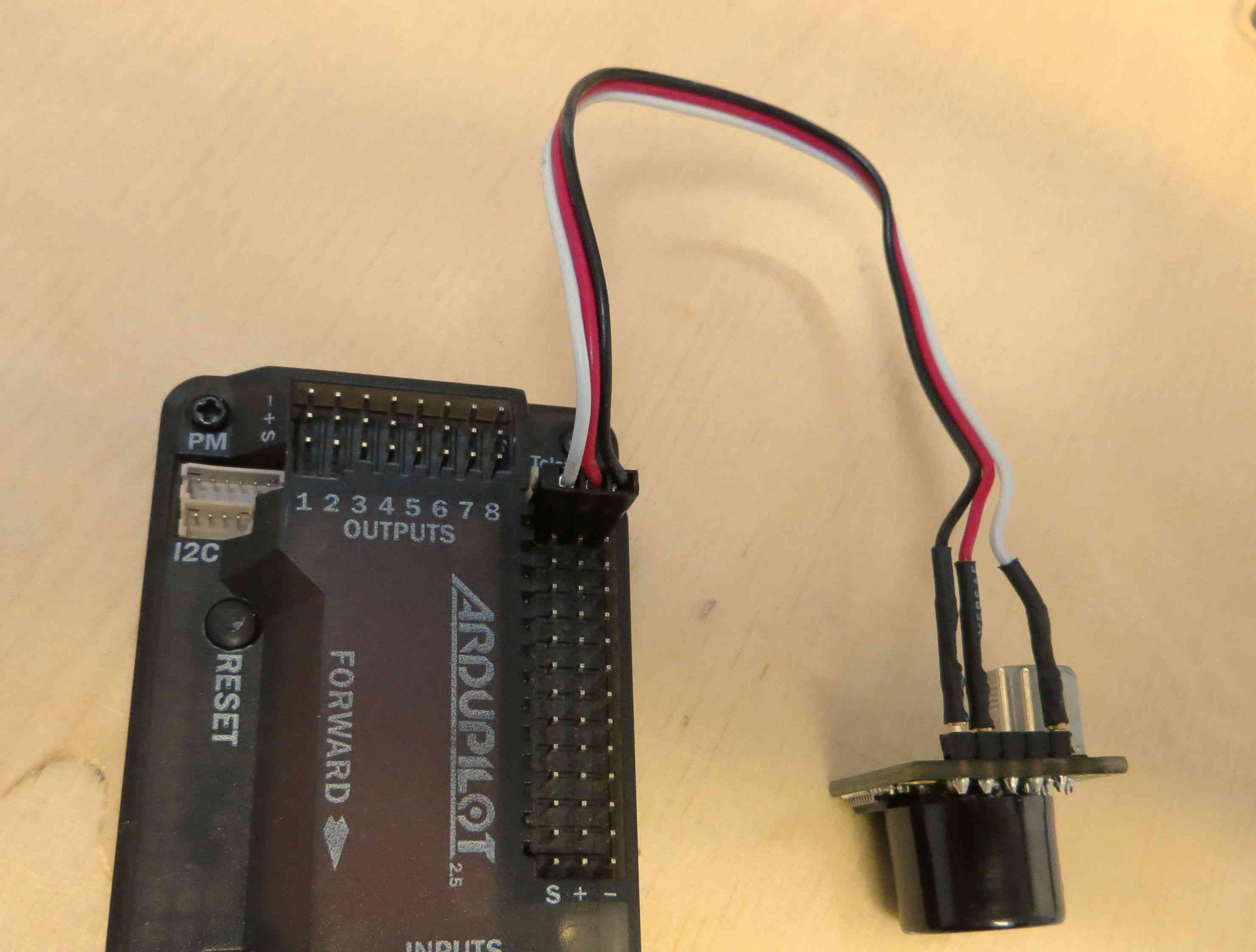
Then plug the servo connector into APM 2’s A0 pins as shown in the picture below. If you’re using a second sonar sensor, plug it into A1.
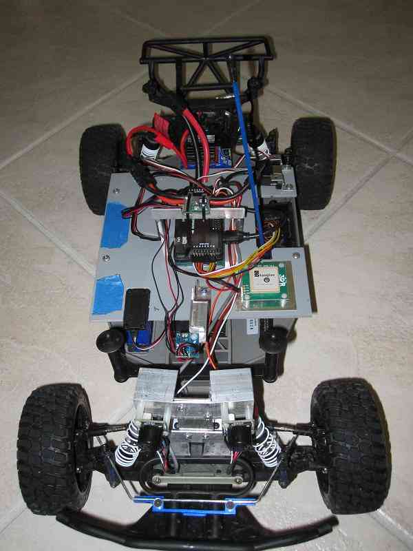
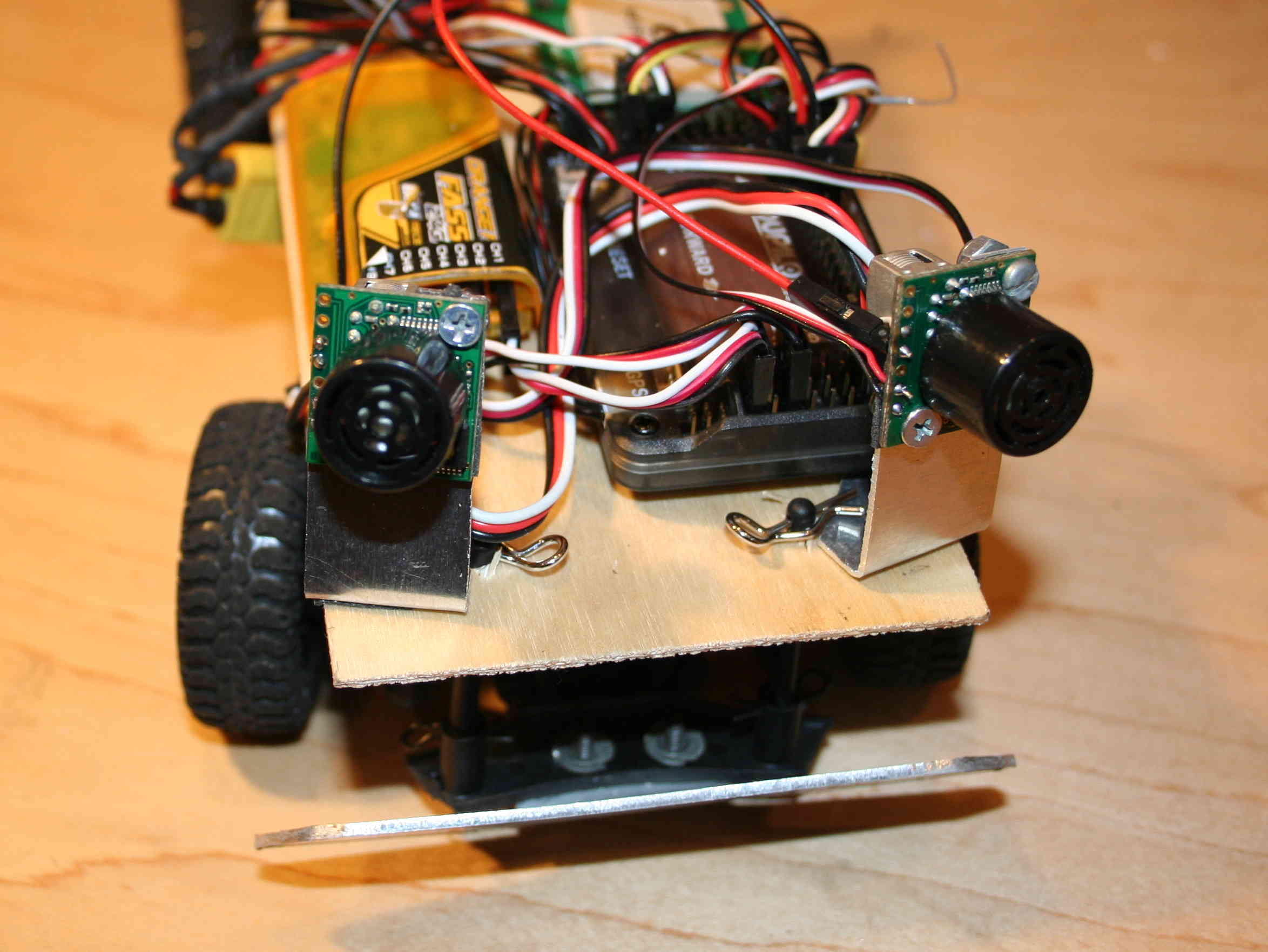
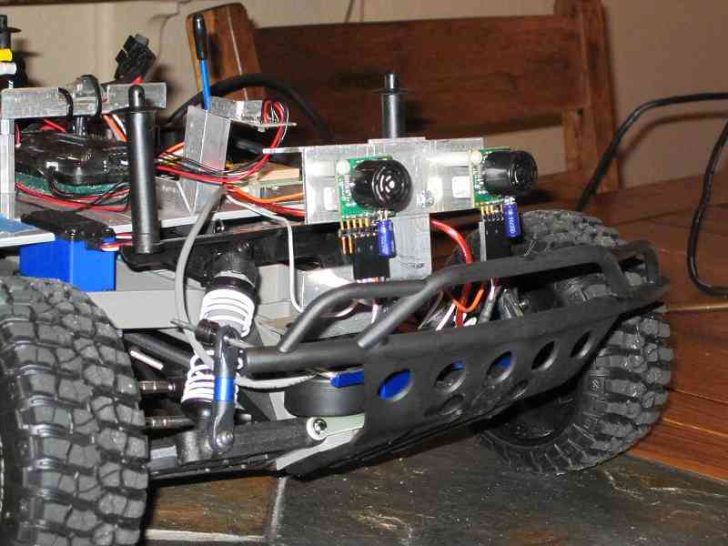
Next, mount your sonar sensor on the front of your rover. To avoid interference from the ground, it should be either raised high off the ground and/or tilted slightly upwards. Below is an example, on a very small rover. The sonar sensor is on the front, nearest to us. The sensor on the other side is an IR sensor, used to compare results.
PX4 Sonar Pins: Sonar is now supported for Rover on PX4FMU/PX4IO. You will need to assign one or both possible Sonars to the appropriate “SONAR_PIN and SONAR2_PIN parameters in: Mission Planner - Configuration - Advanced Params - Adv Parameter List.
The following PX4FMU/PX4IO “Pins” are available for Sonar use.
PIN = 11 : The “airspeed” pin. Located on a 3 pin DF13 connector on the PX4IO board, but directly visible to the ADC on the PX4FMU. This pin can take voltages up to 6.6V (it has an internal voltage divider).
PIN = 12: A general analog input pin. Located on pin 3 of the “FMUSPI” port on the PX4IO board, this pin is directly visible to the PX4FMU analog input code. This can take voltages up to 3.3V.
PIN = 13: A general analog input pin. Located on pin 4 of the “FMUSPI” port on the PX4IO board, this pin is directly visible to the PX4FMU analog input code. This can take voltages up to 3.3V. It is being worked on and will be included in this section when it is available.
It is recommended to use the PX4IO board’s FMU-SPI port connector pin 3 (SONAR_PIN = 12) and connector pin 4 (SONAR2_PIN = 13)
Enable sonar in Mission Planner
All configuration can be done via MAVLink parameters in the Mission Planner. There is no need to edit the Rover code itself.
There are two ways to configure the sensors. You can either use the simplified interface in the “Advanced Params” option of the Mission Planner Configuration tab, or, if you want to get into more detailed control of the sensors, you can use the full set of options in the longer “Adv Parameters List”. (Note: Although there is a sonar sensor enable option in the Hardware Options tab, this is just for Copter and Plane and is disabled for Rover. Because the Rover sonar settings are more detailed and have more options, they must be set in the Advanced lists)
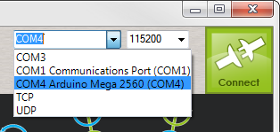
First, connect to Rover via USB or 3DR radio with the Mission Planner. Remember, select 115200 as the baud rate for USB or 57600 for the 3DR wireless radios.
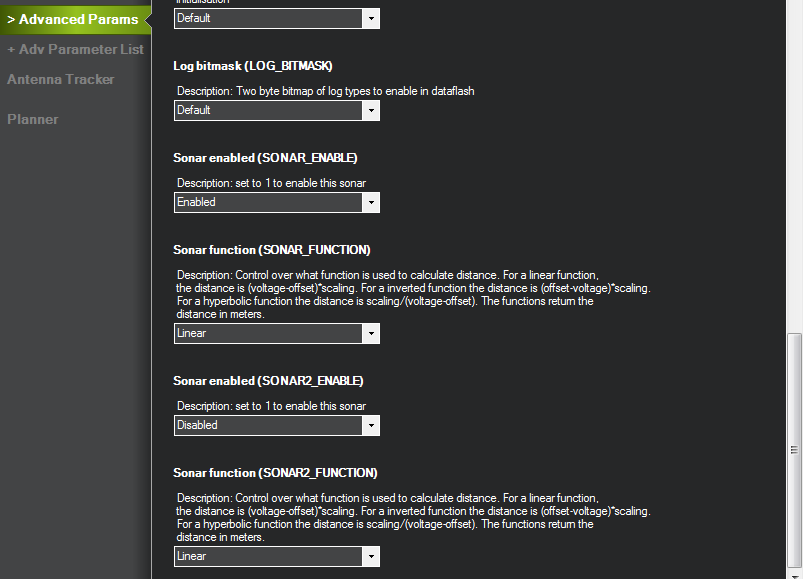
Once you’ve done that, go to the Configuration tab and select the Advanced Params option. Set “Sonar enabled” to enabled. (If you’re using a second sonar sensor, we’ll set that up in the next step.)
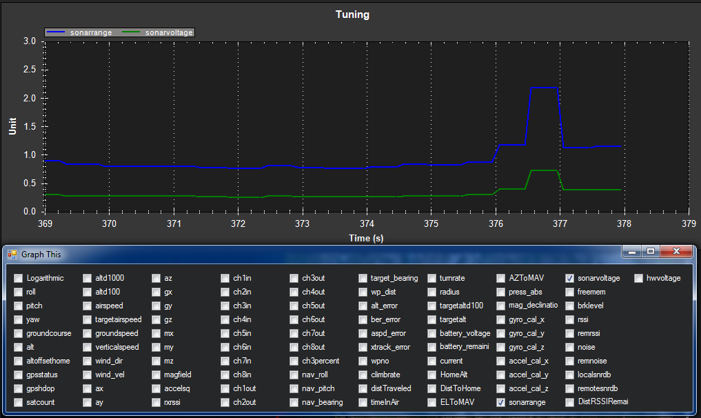
At this point, you should be able to see the sonar data in the Flight Data screen. Look for the little “Tuning” checkbox on the right side, under the map view, and check it. This will bring up the data window. Click on legend and this will bring up the “Graph This” window of data fields to display. Unselect everything but “sonarrange” and “sonarvoltage”. At this point it should start displaying the real-time data from your primary sonar sensor, as shown below:
Enabling a second sonar sensor
Having two sonar sensors tells APM:Rrover which way to turn to avoid an obstacle. If the obstacle is on the right, it turns left and vice versa. This is a little tricky to set up, but well worth it for reliable autonomy.
Physical mounting:
Mount the two sensors facing about 10-15 degrees out from the front of the rover, and 10-15 degrees up from the horizontal, so they don’t see the road/ground. You should also mount them raised as high as you can, to avoid noise from ground reflections. In the picture below, they are raised as high as they can be and still comply with the 4” height limit of the Sparkfun AVC competition Micro category rover.
If you’re going to use aluminium mounts as shown below, make sure you have double-sided foam tape on the back of the sensors so they don’t ground out on the metal mounts.
Mount Sonar to Rover
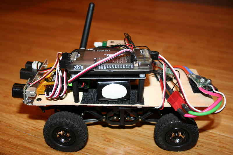
The picture below shows twin sonar sensors mounted to Tom Coyle’s Slash Rover (winner of the AVC 2013 Peloton Class). The shielded signal cable and capacitor (see section on power filtering) can be seen on the rover.
Electrical connections:
You can use any ports you want (A0-A8), but here’s the way we do it: Connect the left sensor’s connector to A0, and the right to A1.
You’re also going to need to connect a wire from each sensor’s control pin to APM so it can tell the sensors when to read, so they don’t both read at the same time and get echoes from each other’s signals (this is explained in the Maxbotix datasheet here). To do this, solder a wire from each sensor’s pin #4 to a cable with a connector on the end that you can plug into APM, as shown below. We use standard jumper cables for this.
Software setup:
First, if you’re using a second sonar sensor, you need to tell the software what APM pins it is connected to. You can do that in the Adv Parameters List in the “SONAR2_PIN” parameter (scroll down to the parameters that begin with SONAR). Typically you will set that to 1 and connect your second sonar sensor to APM 2.5’s A1 port.
Likewise for the “stop pins” that APM uses to control when the sonar sensors fire, to ensure that they don’t interfere with each other. We use A2 for Sonar 1 (left) and A3 for Sonar 2 (right).
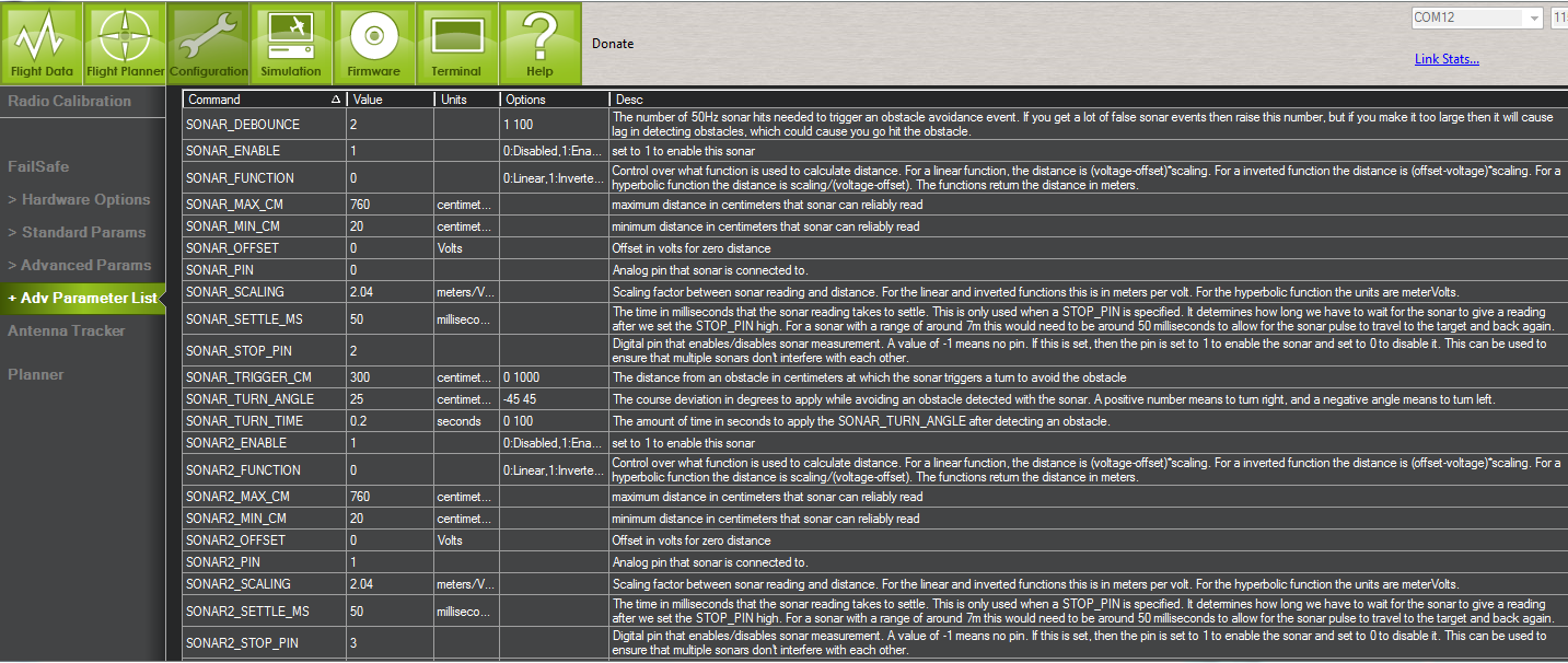
The rest of the parameters shown below are appropriate for the recommended MB1240 sensors. Here are a few other parameters you’ll want to review and set as appropriate for your setup:
SONAR_TRIGGER is the distance at which you want the sonar to start to cause a steering deviation when an object is detected. We typically use 300cm (3 meters)
SONAR_SCALING is the value used to convert the input voltage into distance. Since we use the MB1240 sonar, our scaling parameter is 2.04 which is based on 4.9mv/cm @5vdc.
SONAR_TURN_ANGLE is the angle, in degrees, the steering will make when the trigger distance is detected. A positive value will cause a right turn and a negative value will cause a left turn when only one sonar is in use. We typically use 25 degrees for that.
SONAR_TURN_TIME is the amount of time that the steering will deviate when the trigger distance is detected. Defaults to 1 sec. We’ve actually used a smaller value (0.2 seconds) in the below so it doesn’t turn away as long (we just want it to veer, not turn around)
All of these parameters, along with the others not documented here, are fully described in the Parameters List here.
Testing your sonar setup
The best way to test your sonar is by driving your rover around in Steering mode.
Steering Mode:
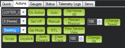
The best way to test both your settings and the physical placement of your sensors is in “Steering Mode”, which will let you drive around in manual RC mode but will override you when the sensors detect an obstacle. Either assign that mode to a position on your RC Mode Switch or select it via the Mission Planner over the wireless telemetry link by using the Actions box on the Mission Planner Flight Data screen as shown below.
When you’re in this mode, approach obstacles and ensure that the rover steers away as you expect. A few troubleshooting tips:
If the rover detects phantom obstacles while just moving on open ground, try one or more of the following:
Tilt the sensors up a bit more so they don’t see the ground
Raise the SONAR_DEBOUNCE parameter from the default of 2 (50hz detections)
Turn the detection range a bit down from 300 cm
Power filtering (optional)
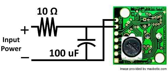
If you’re getting a lot of electrical noise on your sensor (from you rover’s motors or the other electronics) you can improve performance markedly by adding a simple filter.
To avoid spikes in the sonar data you should connect with a shielded cable and include a cap and resistor to filter the power to the sonar as described in this tutorial on techniques to reduce noise and improve sensor performance. Maxbotics sells the necessary components here.
This image shows Slash Rover’s twin sonars and shielded cables as part of a power filtering setup.