Electro-Permanent Magnet (Zubax EPM)
This page explains how to connect a Zubax FluxGrip electro-permanent magnet to an autopilot over DroneCAN. FluxGrip can be controlled using ArduPilot’s DroneCAN virtual-relay support, so no custom firmware or Lua script is required.
Note
This procedure was tested with ArduCopter 4.7.0 and FluxGrip firmware
revision 502e1f5. See the FluxGrip integration forum post
for additional instructions, videos, and troubleshooting information.
Connecting FluxGrip
Connect FluxGrip to the autopilot’s CAN1 port. Follow the DroneCAN wiring and termination instructions.
An external power supply for FluxGrip is recommended. Switching the magnet can briefly draw a large current; a separate supply speeds up switching and avoids loading the autopilot’s peripheral power rail. Refer to the FluxGrip reference manual for its power supply requirements.
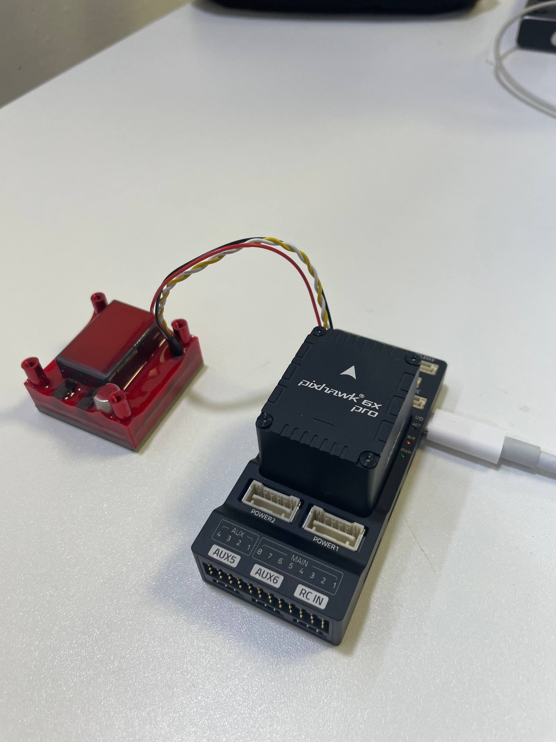
FluxGrip connected to CAN1 on a Pixhawk 6X Pro.
Configuring DroneCAN
In Mission Planner, connect to the autopilot and open Config > Full Parameter List.
Set CAN_P1_DRIVER to
1. Select Write Params and then Refresh Params so the parameters for driver 1 become visible.Set CAN_P1_BITRATE to
1000000and CAN_D1_PROTOCOL to1(DroneCAN).Write the parameters and reboot the autopilot.
This maps physical port CAN1 to virtual CAN driver 1, with DroneCAN as the driver protocol.
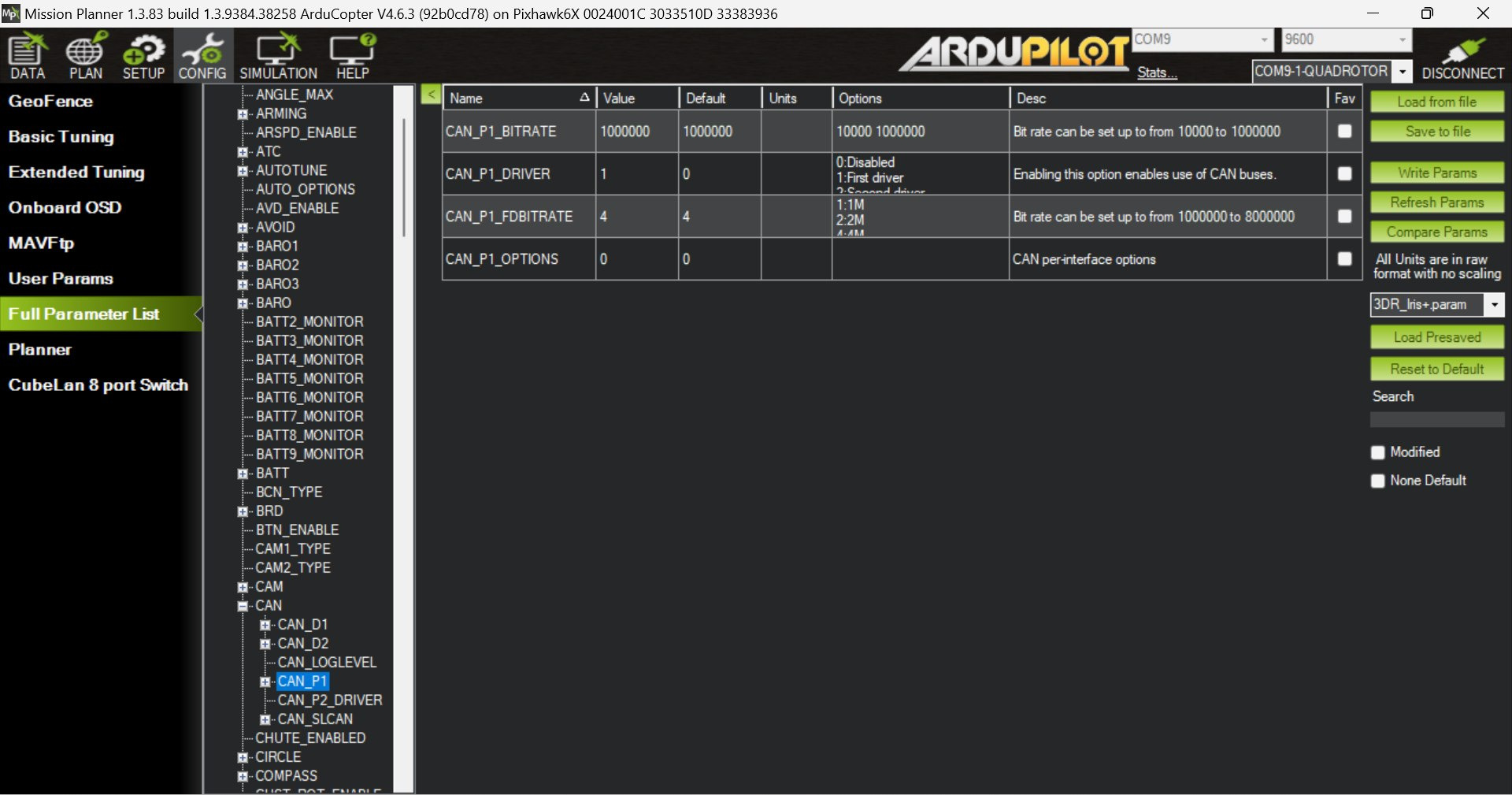
CAN1 configured to use DroneCAN driver 1.
After rebooting, reconnect and refresh the full parameter list. Set:
CAN_D1_UC_NODE to an unused DroneCAN node ID, for example
10.CAN_D1_UC_RLY_RT to
10to transmit remote relay state at 10 Hz.
Write the parameters and reboot the autopilot again.
Note
If FluxGrip is connected to another CAN port or that port is assigned to
another virtual driver, use the corresponding CAN_Px_ and CAN_Dx_
parameters instead.
Verifying DroneCAN communication
When communication is working, FluxGrip’s CAN indicators show one steady indicator for the connection and one blinking indicator for CAN traffic.
In Mission Planner, open Setup > Optional Hardware > DroneCAN/UAVCAN,
select MAVLinkCAN1, and select Connect. FluxGrip should appear in the
node list.
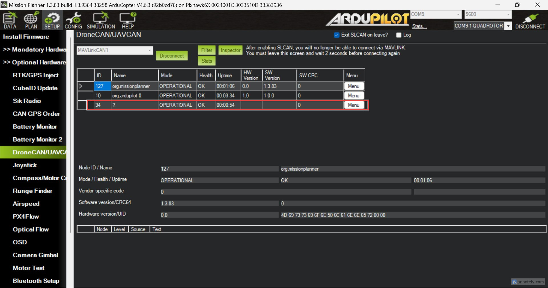
FluxGrip visible as a DroneCAN node in Mission Planner.
If FluxGrip does not appear, check the CAN wiring, bus termination, bitrate, power supply, and the parameters above.
Warning
On a Pixhawk 6X Pro, an IOMCU firmware update error may stop startup before
CAN is initialized. Setting BRD_IO_ENABLE to 2
enables the IOMCU without attempting an update and can be used for bench
diagnosis. Do not fly with an unresolved IOMCU firmware problem.
Configuring FluxGrip as a DroneCAN relay
FluxGrip uses DroneCAN hardpoint ID 0. ArduPilot maps this hardpoint to virtual relay pin 1000.
Set RELAY1_FUNCTION to
1(Relay), select Write Params, and then select Refresh Params.Set the remaining relay parameters:
RELAY1_PIN =
1000(DroneCAN hardpoint ID 0)RELAY1_DEFAULT =
2(NoChange)RELAY1_INVERTED =
0GRIP_ENABLE =
0
Write the parameters and reboot the autopilot.
This configuration uses the relay subsystem instead of ArduPilot’s gripper
backend. Use relay controls and DO_SET_RELAY rather than DO_GRIPPER.
Controlling FluxGrip
FluxGrip can be tested while the vehicle is disarmed. In Mission Planner, open Data > Servo/Relay and operate the first relay:
High/On magnetizes FluxGrip to grip and hold the payload.
Low/Off demagnetizes FluxGrip to release the payload.
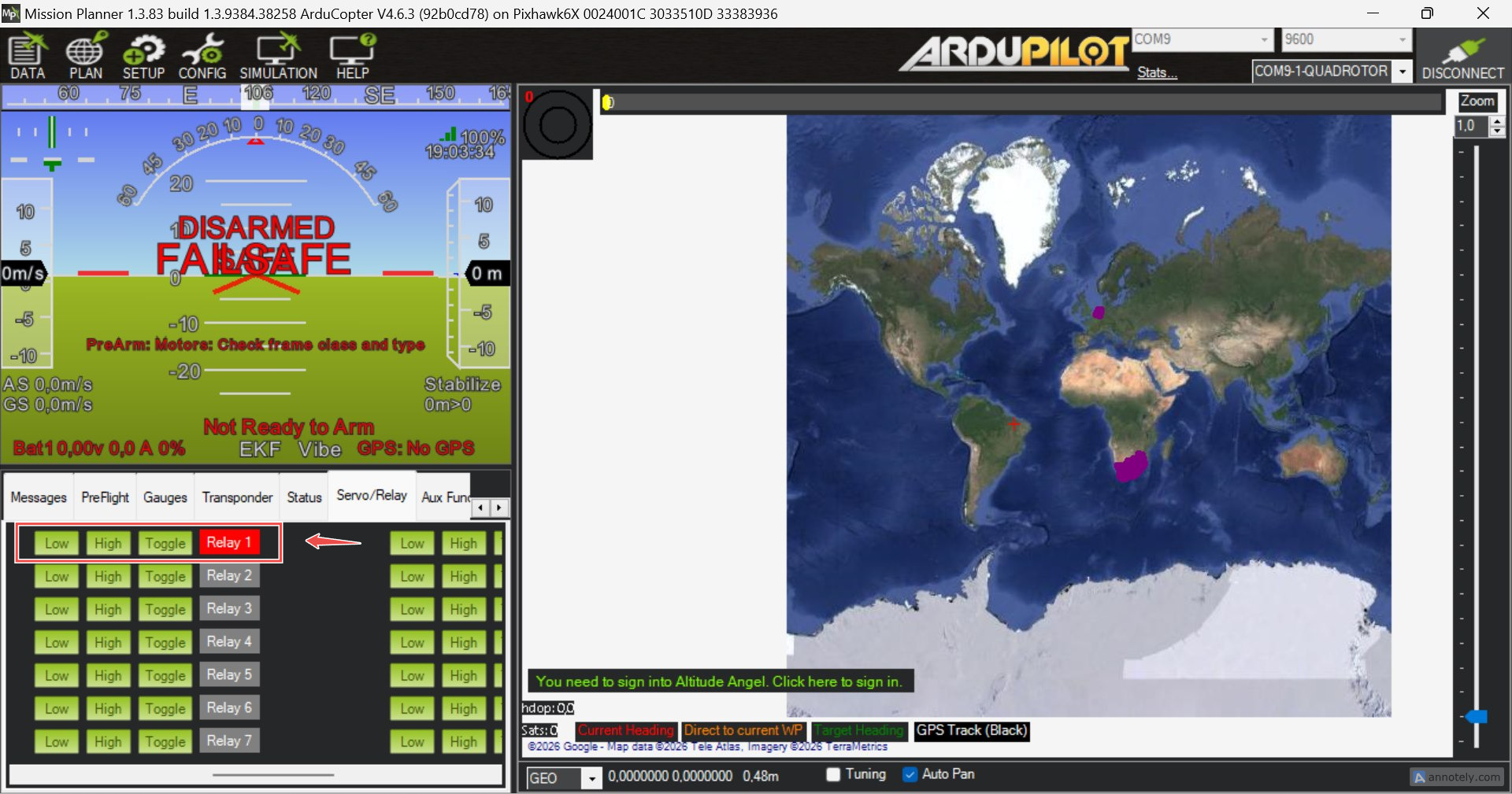
Controlling FluxGrip using the first relay in Mission Planner.
For mission control, add a MAV_CMD_DO_SET_RELAY command with relay number 0 and set its state to
1 to grip or 0 to release. For pilot control, set an RCx_OPTION
to Relay 1 On/Off. See Relay Switch for more relay control
options.
Note
ArduPilot parameters name the first relay RELAY1, while MAVLink numbers
the same relay as relay 0.
Before flight, test both grip and release with the intended payload and power supply. At startup the magnet may report an unknown/detect state, so command and verify the desired state. A rapidly blinking magnet status indicator means that magnetization failed; contact Zubax Robotics for assistance.