NarinFC-X3 VOLOLAND Inc.
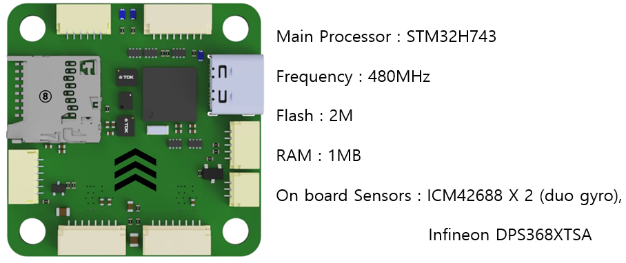
The NarinFC-X3 is a flight controller produced by VOLOLAND Inc. NarinFC-X3 is an advanced autopilot family designed in-house by VOLOLAND Inc. It uses a higher-performance STM32H7 processor and integrates industrial-grade sensors. Compared with previous autopilots, it has better performance and higher reliability.
Features/Specifications
- Processor
STM32H743
- Sensors
Accelerometer/Gyroscope: ICM-42688 * 2
Barometer: DPS368XTSA1
- Interfaces
12 * PWM servo outputs
1 * I2C buses
1 * CAN bus ports
5 * UART
1 * USB Type-C
1 * MicroSD card
JST Connector (SH1.0)
- Power
Input Power 6VDC ~ 36VDC (2S ~ 8S)
- Output Power
3.3V DC 0.5A
5V DC 2.5A
9V DC 2.5A
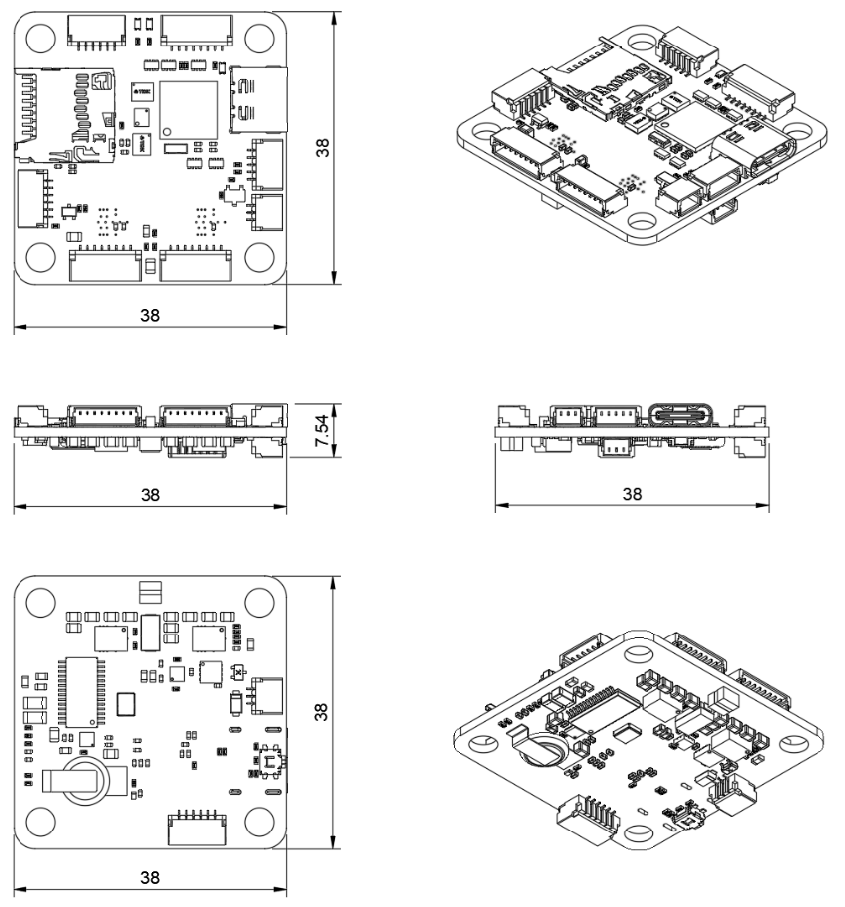
- Size and Dimensions
38mm x 38mm ( mount hole 30.5mm * 30.5mm)
8g
Where to Buy
Outline Dimensions
UART Mapping
SERIAL0 -> USB (MAVLink2)
SERIAL1 -> UART1 (RX1 is SBUS in HD VTX connector)
SERIAL2 -> UART2 (GPS, DMA-enabled)
SERIAL3 -> UART3 (DisplayPort, DMA-enabled)
SERIAL4 -> UART4 (MAVLink2, Telem1)
SERIAL6 -> UART6 (RC Input, DMA-enabled)
SERIAL7 -> UART7 (MAVLink2, Telem2, DMA and flow-control enabled)
SERIAL8 -> UART8 (ESC Telemetry, RX8 on ESC connector for telem)
Serial protocols can be adjusted to personal preferences.
Connectors and Pinouts
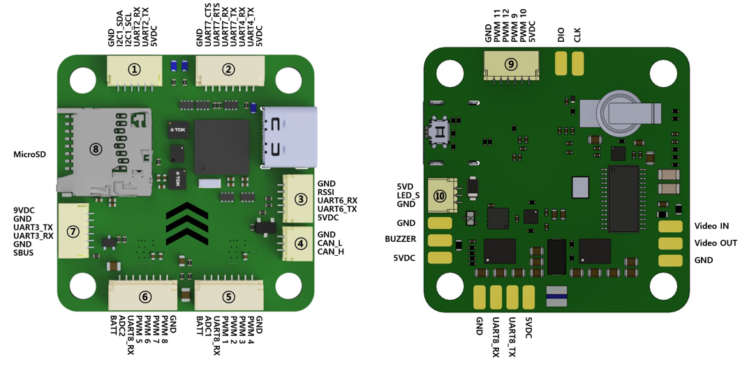
1. I2C, UART2 Port
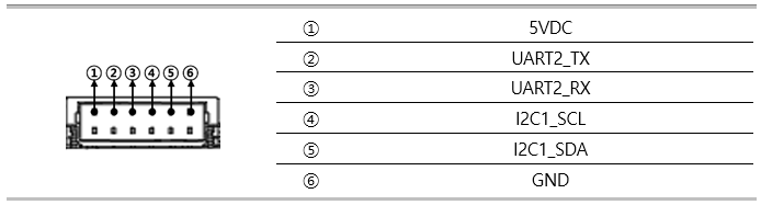
I2C1
UART 2: Ardupilot port Serial2 GPS1
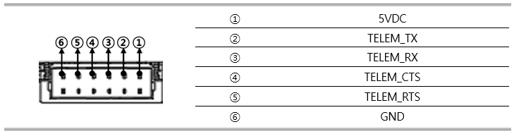
2. UART 4, UART 7 Port
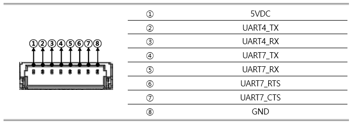
UART 4: Ardupilot port Serial4 Telem_1
UART 7: Ardupilot port Serial7 Telem_2
3. UART 6, RSSI Port
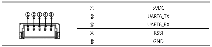
UART 6: Ardupilot port Serial6 Receiver
4. CAN Port
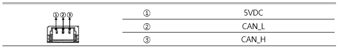
JST GH 6P connector
5. PWM Port-1

PWM 1 ~ PWM 4
UART8_RX
ADC 1
BATT Input
6. PWM Port-2
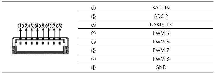
PWM 5 ~ PWM 8
UART8_RX
ADC 2
BATT Input
7. UART 3 Port
UART 3: Ardupilot port Serial3 MSP Display Port
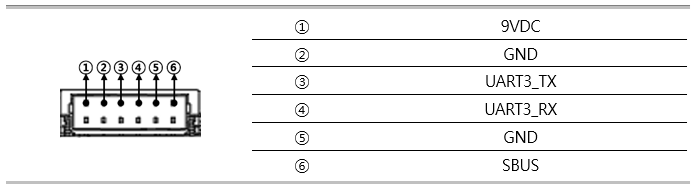
2.54mm pitch DuPont connector
RC_IN : Remote control receiver
8. MicroSD Card Slot
9. PWM Port-3
PWM 9 ~ PWM 12
10. DEBUG & UART7 Port

JST GH 6P connector
DEBUG NODMA
RC Input
RC input is configured by default via the USART6 RX input. It supports all serial RC protocols except PPM.
Note
If the receiver is FPort the receiver must be tied to the USART6 TX pin , RSSI_TYPE set to 3, and SERIAL6_OPTIONS must be set to 7 (invert TX/RX, half duplex).
For full duplex like CRSF/ELRS use both RX6 and TX6 and set RSSI_TYPE also to 3.
If SBUS is used on HD VTX connector (DJI TX), then SERIAL1_PROTOCOl should be set to “23” and SERIAL6_PROTOCOL changed to something else.
FrSky Telemetry
FrSky Telemetry is supported using an unused UART, such as the T1 pin (UART1 transmit).
You need to set the following parameters to enable support for FrSky S.PORT: - SERIAL1_PROTOCOL = 10 - SERIAL1_OPTIONS = 7
OSD Support
The NarinFC-X3 supports analog OSD using its internal MAX7456 and simultaneously DisplayPort using TX3/RX3 on the HD VTX connector.
PWM Output
The NarinFC-X3 supports up to 13 PWM outputs. Outputs 1-10 support DShot and Bi-Directional DShot. The pads for motor output M1 to M4 are provided on both the motor connectors and on separate pads, plus M9-13 on a separate pads for LED strip and other PWM outputs.
The PWM is in 4 groups:
PWM 1-2 in group1
PWM 3-4 in group2
PWM 5-6 in group3
PWM 7-10 in group4
PWM 11-12 in group5
PWM 13 in group6
Channels within the same group need to use the same output rate. If any channel in a group uses DShot then all channels in the group need to use DShot. ALL outputs within the same group need to use the same output rate and protocol.
Battery Monitor
The board has a built-in voltage sensor and external current sensor input. The current sensor can read up to 130 Amps. The voltage sensor can handle up to 6S LiPo batteries.
The correct battery setting parameters are:
BATT_VOLT_PIN = 10
BATT_CURR_PIN = 11
BATT_MONITOR = 4
BATT_VOLT_MULT = 11.0
BATT_AMP_PERVLT = 40.0
Pads for a second analog battery monitor are provided. To use:
BATT2_VOLT_PIN = 18
BATT2_CURR_PIN = 7
BATT2_VOLT_MULT = 11.0
Analog RSSI and AIRSPEED inputs
Analog RSSI uses RSSI_ANA_PIN = 8
Analog Airspeed sensor would use ARSPD_PIN = 4
Compass
The NarinFC-X3 does not have a builtin compass.
Firmware
Firmware for this board can be found here in sub-folders labeled “NarinFC-X3”
Loading Firmware
This board comes with ArduPilot firmware pre-installed and other vehicle/revision ArduPilot firmware can be loaded using most Ground Control Stations.
Firmware for these boards can be found https://firmware.ardupilot.org in sub-folders labeled “NarinFC-X3”.
The board comes pre-installed with an ArduPilot bootloader, allowing the loading of *.apj firmware files with any ArduPilot compatible ground station, such as Mission Planner.