Mateksys H743-Wing/SLIM/MINI/WLITE
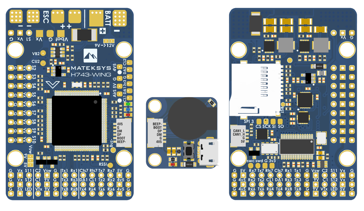
the above image and some content courtesy of mateksys.com
Note
Only the WING version is shown above. All versions use the same firmware, but have varying configurations for pinouts and resources available. See Matek’s site for exact details for every variant.
Specifications
Processor
STM32H743VIT6 ARM (480MHz)
Sensors
InvenSense MPU6000 IMU (accel, gyro) & ICM20602
DPS310 barometer
Voltage & 132A current sensor (integrated current sensor only on -WING V2/V3 and -WLITE)
Power
9V ~ 36V DC input power
5V 2A BEC for peripherals
9/12V 2A BEC for video
5/6/7.2V 8A BEC for servos
Interfaces
7x UARTS
13x PWM outputs
1x RC input PWM/PPM, SBUS
2x I2C ports for external compass, airspeed sensor, etc.
SPI4 port
USB port (with remote cabling)
CAN port
6 ADC
Buzzer and Safety Switch
Dual Switchable Camera inputs
Built-in OSD
microSD card
Second battery monitor input pins
Size and Dimensions
tbd mm x tbd mm x tbd mm
tbd g
Camera and Supply Switch
Switching between the two camera inputs, C1 (default on) or C2, and between on (default) and off of Vsw (jumper selectable supply), can be implemented using the Relay function of ArduPilot and assigning the relays to an RCx_OPTION switch on the transmitter.
Set the RELAYx_PIN to “81” for on/off of Vsw, and to “82” to control the camera switching.
Then select an RC channel for control (Chx) and set its RCx_OPTION to the appropriate Relay (1-4) that you had set its pin parameter above.
For example, use Channel 10 to control the camera switch using Relay 2:
RELAY2_PIN = “82”
RC10_OPTION = “34” (Relay2 Control)
Note
setting Relay on/high assigned for Vsw will turn off that supply. Likewise, setting on/high for the Relay assigned for camera, will switch from Camera 1 to Camera 2.
Default UART order
SERIAL0 = console = USB
SERIAL1 = Telemetry1 = UART7 (support CTS and RTS signaling)
SERIAL2 = Telemetry2 = USART1
SERIAL3 = GPS1 = USART2
SERIAL4 = GPS2 = USART3
SERIAL5 = USER = UART8
SERIAL6 = USER = UART4
SERIAL7 = USER = UART6 (TX only unless BRD_ALT_CONFIG = 1, then RX available also)
Serial port protocols (Telem, GPS, etc.) can be adjusted to personal preferences.
RC Input
The Rx6 pin, which by default is mapped to a timer input, can be used for all ArduPilot supported receiver protocols, except CRSF/ELRS and SRXL2 which require a true UART connection. However, FPort, when connected in this manner, will only provide RC without telemetry.
To allow CRSF and embedded telemetry available in Fport, CRSF, and SRXL2 receivers, the Rx6 pin can also be configured to be used as true UART RX pin for use with bi-directional systems by setting the BRD_ALT_CONFIG to “1” so it becomes the SERIAL7 port’s RX input pin.
With this option, SERIAL7_PROTOCOL must be set to “23”, and:
PPM is not supported.
SBUS/DSM/SRXL connects to the R6 pin, but SBUS requires that the SERIAL7_OPTIONS be set to “3”.
FPort requires connection to Tx6 and SERIAL7_OPTIONS be set to “7”.
CRSF also requires a Tx6 connection, in addition to Rx6, and automatically provides telemetry. Set SERIAL7_OPTIONS to “0”.
SRXL2 requires a connection to Tx6 and automatically provides telemetry. Set SERIAL7_OPTIONS to “4”.
Any UART can be used for RC system connections in ArduPilot also, and is compatible with all protocols except PPM. See Radio Control Systems for details.
Dshot capability
All motor/servo outputs are Dshot and PWM capable. However, mixing Dshot and normal PWM operation for outputs is restricted into groups, ie. enabling Dshot for an output in a group requires that ALL outputs in that group be configured and used as Dshot, rather than PWM outputs. The output groups that must be the same (PWM rate or Dshot, when configured as a normal servo/motor output) are: 1/2, 3/4/5/6, 7/8/9/10, 11/12, and 13 (LED).
Where to Buy
see this list of Mateksys Distributors
Connecting a GPS/Compass module
This board does not include a GPS or compass so an external GPS/compass should be connected in order for autonomous modes to function.
If the GPS is attached to UART2 TX/RX and powered from the adjacent 4.5V pins, it will be powered when connected via USB, as would the RX if powered from the adjacent 4.5V pins to UART6.
A battery must be plugged in for power to be provided to the pins marked 5V on the board.
Battery Monitor Settings
These should already be set by default. However, if lost or changed:
Enable Battery monitor with these parameter settings :
BATT_MONITOR =4
Then reboot.
BATT_VOLT_MULT 10.5 (note: WLITE needs this changed to 21)
BATT_AMP_PERVLT 40.0 (note: WLITE and WING V2/V3 needs this changed to 66.7)
BATT2_VOLT_MULT 11.0
Note
this autopilot uses a high precision current sensor which is sensitive to ESC switching noise. Be sure to use the bypass capacitor provided. In some cases, the ESCs themselves will need additional 200-330uF low ESR capacitors on their power inputs, if they do not incorporate them already. See Matek FAQs for more information.
Firmware
Firmware for these boards can be found here in sub-folders labeled “MatekH743”.
Firmware that supports bi-directional Dshot is labeled “MatekH743-bdshot”.
Warning
The bi-directional Dshot firmware redefines the Rx6 pin as a pure UART input, and cannot support PPM. It also requires that the SERIAL7_PROTOCOL = 23 and that SERIAL7_OPTIONS = 3 for use with SBUS to provide inversion. In addition, outputs 9-12 no longer support normal Dshot. Only outputs 1-8 are bi-directional Dshot capable, with 1-2,3-4,5-6,7-8 in groups. Finally, the buzzer in the USB dongle will no longer play musical tones, only simple buzzer beeps.
Loading Firmware
Initial firmware load can be done with DFU by plugging in USB with the bootloader button pressed. Then you should load the “with_bl.hex” firmware, using your favorite DFU loading tool.
Once the initial firmware is loaded you can update the firmware using any ArduPilot ground station software. Updates should be done with the “*.apj” firmware files.
Note
If you experience issues with the device ceasing to initialize after power up, see When Problems Arise section for H7 based autopilots for a possible solution.