Foxeer H7 MPU6000
Where to Buy
Specifications
Processor
STM32H743 ARM (480MHz)
AT7456E OSD
16MB data logging flash
Sensors
MPU-6000 IMU (accel, gyro)
DPS310 barometer
Power
4S - 8S Lipo input voltage with voltage monitoring
10V, 2A BEC for powering Video Transmitter
5V, 2A BEC for internal and peripherals
Interfaces
9x PWM outputs Bi-Directional DShot capable (Serial LED output is PWM9)
1x RC input
7x UARTs
I2C port for external compass, airspeed, etc.
USB-C port
Size and Dimensions
37mm x 372mm x 19mm
7.8g
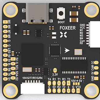
Wiring Diagram

Default UART Order
The UARTs are marked Rn and Tn in the above pinouts. The Rn pin is the receive pin for UARTn. The Tn pin is the transmit pin for UARTn.
SERIAL0 -> USB
SERIAL1 -> USART1 (Serial RC input) (DMA capable)
SERIAL2 -> USART2 (Tramp protocol by default)
SERIAL3 -> UART3 (User, no protocol set by default) (DMA capable)
SERIAL4 -> UART4 ((RX on DJI connector for RC,no protocol by default)(DMA capable)
SERIAL6 -> UART6 (GPS) (DMA capable)
SERIAL7 -> UART7 (on DJI Goggle connector, set by default to DJI protocol)
SERIAL8 -> UART8 (RX only on 4in1 ESC connector, ESC telemetry is the default protocol)
Serial protocols shown are defaults, but can be adjusted to personal preferences.
Servo/Motor Outputs
All motor/servo outputs are Dshot and PWM capable. However, mixing Dshot, serial LED, and normal PWM operation for outputs is restricted into groups, ie. enabling Dshot for an output in a group requires that ALL outputs in that group be configured and used as Dshot, rather than PWM outputs. Outputs 1-8 are also Bi-Directional DShot capable.
PWM 1-4 in group1
PWM 5,6 in group2
PWM 7,8 in group3
PWM 9 in group4 (marked LED)
Note
for users migrating from BetaflightX quads, the first four outputs M1-M4 have been configured for use with existing motor wiring using these default parameters:
FRAME_CLASS = 1 (Quad)
FRAME_TYPE = 12 (BetaFlightX)
RC Input
RC input is configured by default on the R1 (UART1_RX) pin. It supports all serial RC protocols. For protocols requiring separate half-duplex serial to transmit telemetry (such as FPort) you should setup SERIAL1 as an RC input serial port, with half-duplex, pin-swap and inversion enabled (SERIAL1_OPTIONS = 15).
The DJI connector also has UART4 RX input for DJI RC input. To use this you would need to set SERIAL1_PROTOCOL to something other than “23” (RCinput) and set this protocol for SERIAL4_PROTOCOL instead.
For PPM support on UART4_RX set BRD_ALT_CONFIG to 1 and use the UART4 RX pin as PPM (and any other serial RC protocol) input.
OSD Support
The FoxeerH7 MPU6000 supports using its internal OSD using OSD_TYPE 1 (MAX7456 driver). External OSD support such as DJI or DisplayPort is supported using UART7 or any other free UART. See MSP OSD for more info.
VTX Control
UART2 TX is setup to provide IRC Tramp control of video transmitters by default. See Video Transmitter Support for more information.
Camera/GPIO Control
ArduPilot does not support CameraControl but that pin is made available as a GPIO. As is the S1 and S2 pins. Relay operation is possible using any of those three pins. Their designated GPIO pin number for parameter setup is shown below:
S1: GPIO 70
S2: GPIO 71
CC: GPIO 72
Compass
The FoxeerH743 does not have a builtin compass, but you can attach an external compass using I2C on the SDA and SCL pads.
Battery Monitor Configuration
These settings are set as defaults when the firmware is loaded (except BATT_AMP_PERVLT which needs to be changed from the default value). However, if they are ever lost, you can manually set the parameters:
Enable Battery monitor.
BATT_MONITOR =4
Then reboot.
BATT_VOLT_MULT 11.0
BATT_AMP_PERVLT 35.4
Connecting a GPS/Compass module
This board does not include a GPS or compass so an external GPS/compass should be connected in order for autonomous modes to function.
Firmware
This board does not come with ArduPilot firmware pre-installed. Use instructions here to load ArduPilot the first time Loading Firmware onto boards without existing ArduPilot firmware.
Firmware for this board can be found here in sub-folders labeled “FoxeerH743v1”.