PixFlamingo-F767 Flight Controller
The PixFlamingo-F767 is a flight controller produced by Dheeran Labs. Contact dheeranlabs@gmail.com for sales
Specifications
- Processor
STM32F767 32-bit processor
- Sensors
ICM42670, MPU6500/ICM20602 Acc/Gyro
One SPI barometer, either: MS5611/BMP280/DPS310
- Power
5v input voltage with voltage monitoring
3.3V, 1A BEC
- Interfaces
10x PWM outputs, 8DShot capable
1x RC input
5x UARTs/serial for GPS and other peripherals
2x I2C ports for external compass, airspeed, etc.
USB-C port and boot button on separate dongle for ease of access
microSD card slot port
Internal RGB LED
Safety switch port
Buzzer port
Connectors
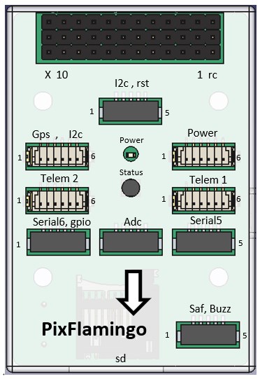
POWER ADC
Pin |
Signal |
Volt |
|---|---|---|
1 |
VCC_IN |
+5V |
2 |
VCC_IN |
+5V |
3 |
BAT_CRRENT_ADC |
+3.3V |
4 |
BAT_VOLTAGE_ADC |
+3.3V |
5 |
GND |
GND |
6 |
GND |
GND |
TELEM1
Pin |
Signal |
Volt |
|---|---|---|
1 |
VCC |
+5V |
2 |
UART_TX3 |
+3.3V |
3 |
UART_RX3 |
+3.3V |
4 |
CTS |
+3.3V |
5 |
RTS |
+3.3V |
6 |
GND |
GND |
TELEM2
Pin |
Signal |
Volt |
|---|---|---|
1 |
VCC |
+5V |
2 |
UART_TX6 |
+3.3V |
3 |
UART_RX6 |
+3.3V |
4 |
X |
X |
5 |
X |
X |
6 |
GND |
GND |
GPS1
Pin |
Signal |
Volt |
|---|---|---|
1 |
VCC |
+5V |
2 |
UART_TX1 |
+3.3V |
3 |
UART_RX1 |
+3.3V |
4 |
I2C2_SCL |
+3.3V |
5 |
I2C2_SDA |
+3.3V |
6 |
GND |
GND |
SERIAL5
Pin |
SignalPixflamingo-F767-pinout.jpg |
Volt |
|---|---|---|
1 |
VCC |
+5V |
2 |
UART_TX7 |
+3.3V |
3 |
UART_RX7 |
+3.3V |
4 |
X |
X |
5 |
GND |
GND |
SERIAL6, GPIO
Pin |
Signal |
Volt |
|---|---|---|
1 |
VCC |
+5V |
2 |
USART_TX2 |
+3.3V |
3 |
USART_RX2 |
+3.3V |
4 |
GPIO |
+3.3V |
5 |
GND |
GND |
SAFETY
Pin |
Signal |
Volt |
|---|---|---|
1 |
SAFETY_SW |
+3.3V |
2 |
SAFETY_SW_LED |
+3.3V |
3 |
3V3_OUT |
+3.3V |
4 |
BUZZER+ |
+3.3V |
5 |
BUZZER- |
GND |
UART Mapping
The UARTs are marked Rn and Tn in the above pinouts. The Rn pin is the receive pin for UARTn. The Tn pin is the transmit pin for UARTn.
SERIAL0 -> USB (OTG1)
SERIAL1 -> UART3 (TELEM1) with CTS/RTS DMA Enabled
SERIAL2 -> UART6 (TELEM2) with DMA Enabled
SERIAL3 -> UART1 (GPS1) Tx(NODMA), Rx(DMA Enabled)
SERIAL4 -> EMPTY
SERIAL5 -> UART7 (User) NODMA
SERIAL6 -> USART2 (User) NODMA
RC Input
The RCIN pin supports all unidirectional protocols supported by ArduPilot including PPM. If bi-directiona protocols are used, like CRSF/ELRS, they will need to use a full UART (DMA capable) instead, set to protocol “23”.
PWM Output
The PixFlamingo-F767 supports up to 10 PWM outputs. The PWM is in 5 groups. IF Dshot is used for an output, all outputs in its group must be DShot.
PWM 1-4 in group1
PWM 5-8 in group2
PWM 9 in group3 (not DShot capable)
PWM 10 in group4 (not DShot capable)
GPIOs
All 10 PWM channels can be used for GPIO functions (relays, buttons, RPM etc).
The GPIO pin numbers for these PWM channels in ArduPilot are shown below:
PWM Channels |
Pin |
PWM Channels |
Pin |
|---|---|---|---|
PWM1 |
50 |
PWM8 |
57 |
PWM2 |
51 |
PWM9 |
58 |
PWM3 |
52 |
PWM10 |
59 |
PWM4 |
53 |
||
PWM5 |
54 |
||
PWM6 |
55 |
||
PWM7 |
56 |
Analog inputs
The PixFlamingo-F767 flight controller has 4 analog inputs
ADC Pin10 -> Battery Current
ADC Pin11 -> Battery Voltage
ADC Pin14 -> ADC 3V3 Sense
ADC Pin15 -> ADC 6V6 Sense
Battery Monitor Configuration
The board has voltage and current sensor inputs on the POWER_ADC connector.
The derfauult battery setting parameters are:
Enable Battery monitor.
BATT_MONITOR =4
Then reboot.
BATT_VOLT_PIN 11
BATT_CURR_PIN 10
BATT_VOLT_MULT 10.1 (may need adjustment if supplied monitor is not used)
BATT_AMP_PERVLT 17.0 (may need adjustment if supplied monitor is not used)
Firmware
Firmware for this board can be found here in sub-folders labeled “PixFlamingo-F767”.
Loading Firmware
The PixFlamingo-F767 flight controller comes pre-installed with an ArduPilot compatible bootloader, allowing the loading of *.apj firmware files with any ArduPilot compatible ground station.