Archived:Rover APM2.x Wiring and Quick Start
Warning
ARCHIVED
The APM2.x is end of life for use with ArduPilot. This article is made available for existing users.
This article explains how to set up Rover using the APM2.x autopilot.
Overview
The process of converting an RC car to a Rover consists of adding an autopilot board in between the RC receiver and the car’s motor and steering servo. We recommend that the controller be powered by the included Power Module.
Note
This tutorial assumes you’re using a Mode 2 radio setup. If you’re using Mode 1, the throttle will move to the other stick
Rover is designed to use regular RC transmitters (not specialized RC car transmitters) with both throttle and steering on the right stick in Mode 1 or left stick in Mode 2 - typically the elevator stick. This is because RC cars can typically go both forwards and backwards and so the throttle should be spring-loaded to return to the mid-point. If however, you are not using a RC car motor controller (ESC) but rather a regular aircraft motor controller (ESC), which typically does not have a reverse function, you can put the throttle on the left stick as would normally be the case for an aircraft.

Powering Rover
The easiest way to power the APM2.x is using a 3DR Power Module with a LiPo battery.
The Power Module will not power servos and other peripherals. For more information/alternatives see Powering the APM2.
RC Setup
Connect your RC system to APM as shown below:
Input Channels:
RC Rx |
APM Input |
Function |
1 |
1 |
Steering |
2 |
3 |
Throttle |
5 |
8 |
Mode |
6 |
7 |
Record waypoint |
Output Channels:
For standard RC cars that use a servo to steer, use the Car settings. If, however, you have a treaded tank or some other vehicle that uses different speed motors on each side to steer, use the Skid Steer settings.
APM Output |
Car |
Skid Steer |
1 |
Servo |
Left Motor |
3 |
Motor/ESC |
Right Motor |
Reassigning your RC transmitter stick channels
The default transmitter stick configuration should be suitable in almost all cases. If you do need to change them, then see RCMAP Input Channel Mapping.
Installing it in your car
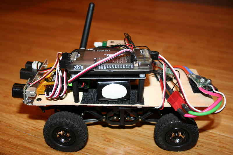
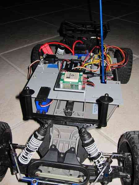
The below shows a typical setup in a small rover, using APM2.x, 3DR radio telemetry and both sonar and IR sensors (instructions on setting them up are here). Note a few elements:
The RC car’s plastic body shell has been removed and a plywood sheet cut and drilled to fit on the mounting posts.
APM2.x has been raised up on a platform made of four 30mm nylon spacers, four 5mm nylon screws, and a Copter stack-up plate. This is to ensure that the sensitive compass sensor on APM is as far as possible from the magnetic noise/interference of the car’s electric motor.
APM, the GPS, 3DR radio and RC receiver are all powered by the APM Power Module (included with the APM set). The car’s steering servo is powered by the car’s speed controller. This is the standard setup and doesn’t require any special settings or configuration, but for those wondering about power, that’s the answer. Among other advantages, the use of the APM Power Module means that APM can do voltage and current sensing and report battery status to the Ground Station during the run, as well as data log it for after-run analysis.
A larger battery than the car was originally designed for is being used (because the rover is designed to travel long distances off-road), and it is mounted on velcro under the APM platform so it doesn’t shift.
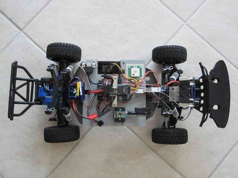
Depending on the car frame you’re using, you may wish to set up your gear differently. Almost any configuration can work, but just remember to keep APM’s far from sources of magnetic interference as possible! The image below shows a top view of Tom Coyle’s Slash Rover (winner of the Peloton Class at AVC 2013) with a Spektrum receiver, GPS, and external compass.
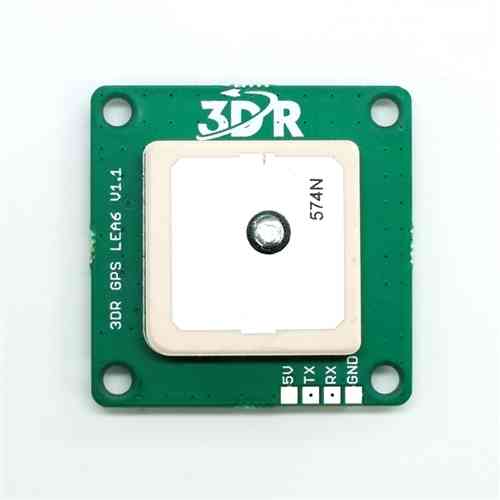
3DR GPS uBlox with Onboard Compass
3DR GPS uBlox with Onboard Compass is intended for use with APM2.x (for external compass). It provides enhanced compass performance because of the freedom to situate the GPS unit in an optimal position independent of the location of the APM.
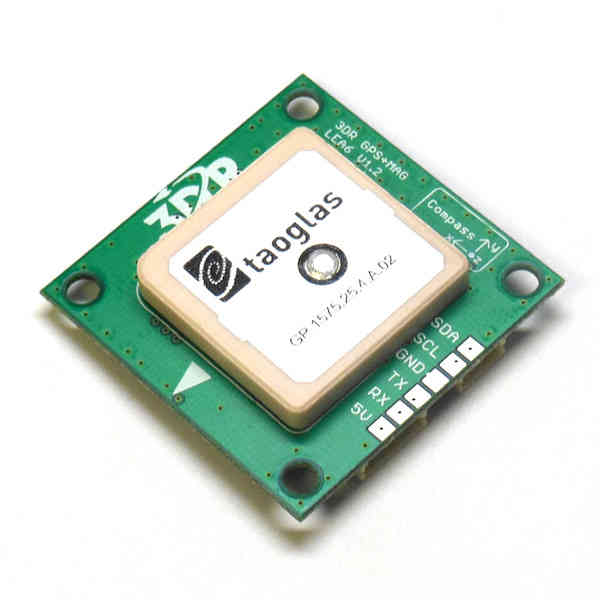
Place your GPS in an elevated position on your rover with the arrow facing forward (toward the front facing direction of your rover). Connect the GPS module to the APM using the two cables included with the GPS as shown below.
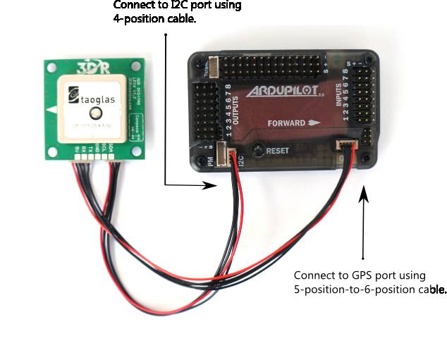
3DR GPS uBlox with Onboard Compass includes two connector cables: one 4-position cable and one 5-position-to-6-position cable. To connect the GPS module to APM, connect the GPS to the APM GPS port using the 5-position-to-6-position cable; connect the GPS to the APM I2C port using the 4-position cable.
Slash Rover’s GPS with external compass mount:
3DR GPS uBlox without Onboard Compass
3DR GPS uBlox without Onboard Compass is intended for use with APM2.x. To install your GPS module without compass, mount to the top of your rover and connect to the APM GPS port using the 5-position-to-6-position connector cable.
Next step: Load the Rover code and configure it