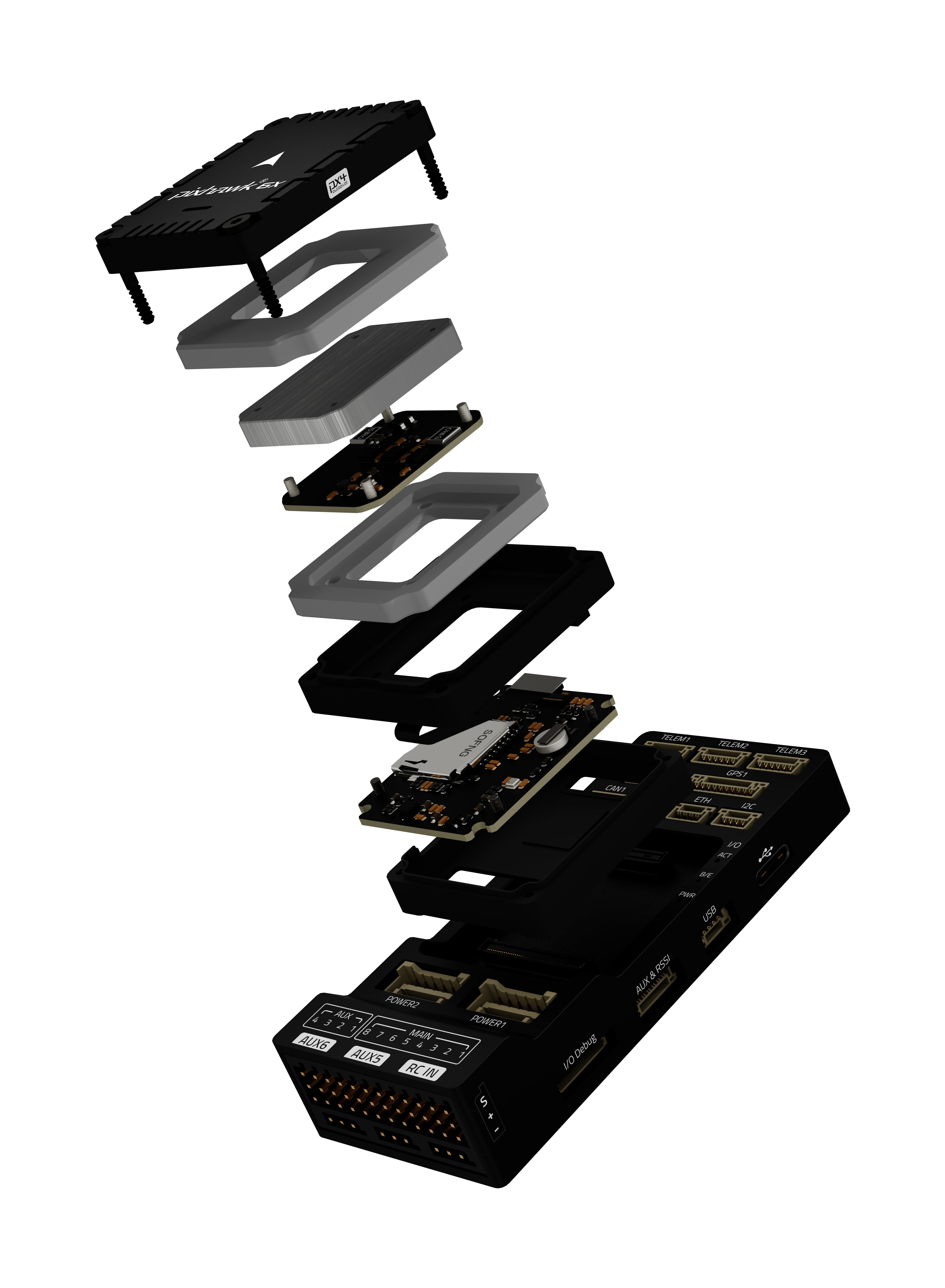
Pixhawk 6X/6X Pro Flight Controller
Pixhawk6X® is the latest update to the successful family of Pixhawk® autopilots made by Holybro, featuring STM32H7 cpus, vibration isolation of IMUs, redundant IMUs, double redundant barometers on separate buses, IMU heating, and integrated Ethernet for high speed connections to companion computers.
Pixhawk6X:
Where To Buy
- The Pixhawk 6X autopilots are sold by Holybro
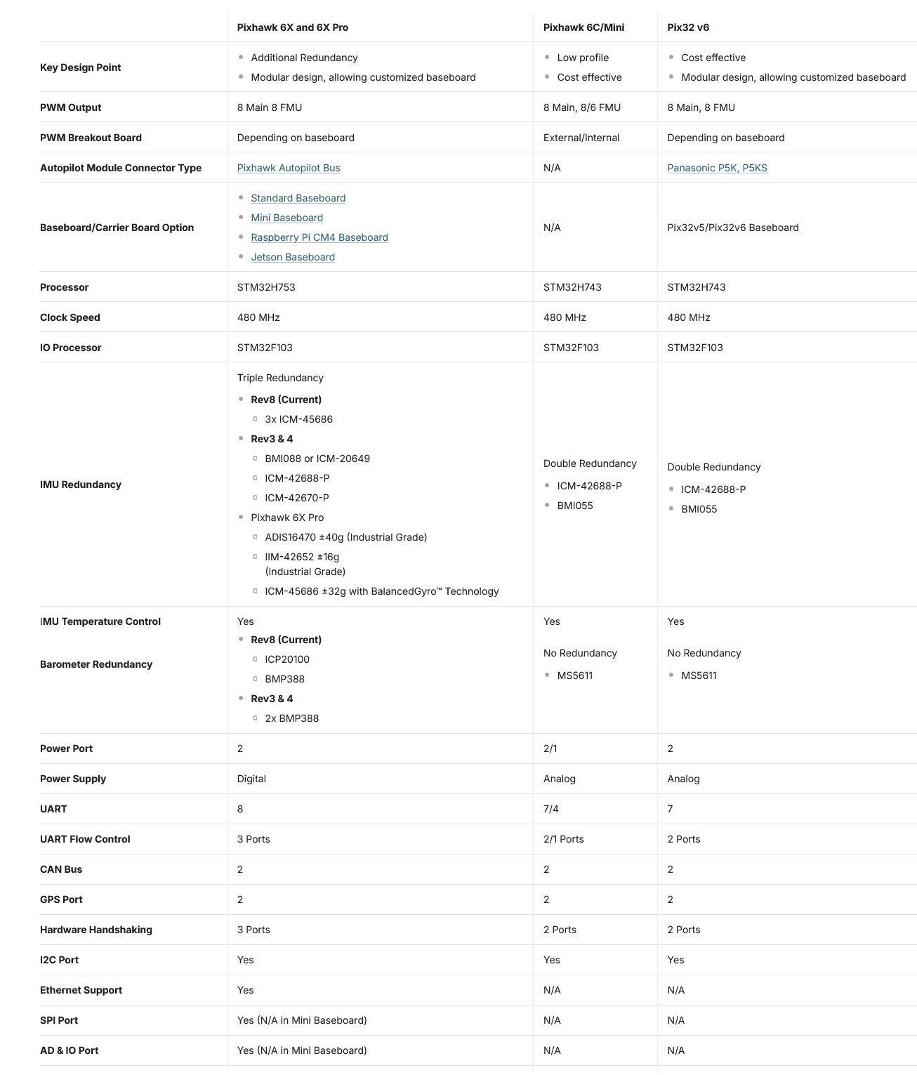
Features of Pixhawk6 Series
(click table below to expand)
Baseboard Pinouts
Typical Wiring Diagram
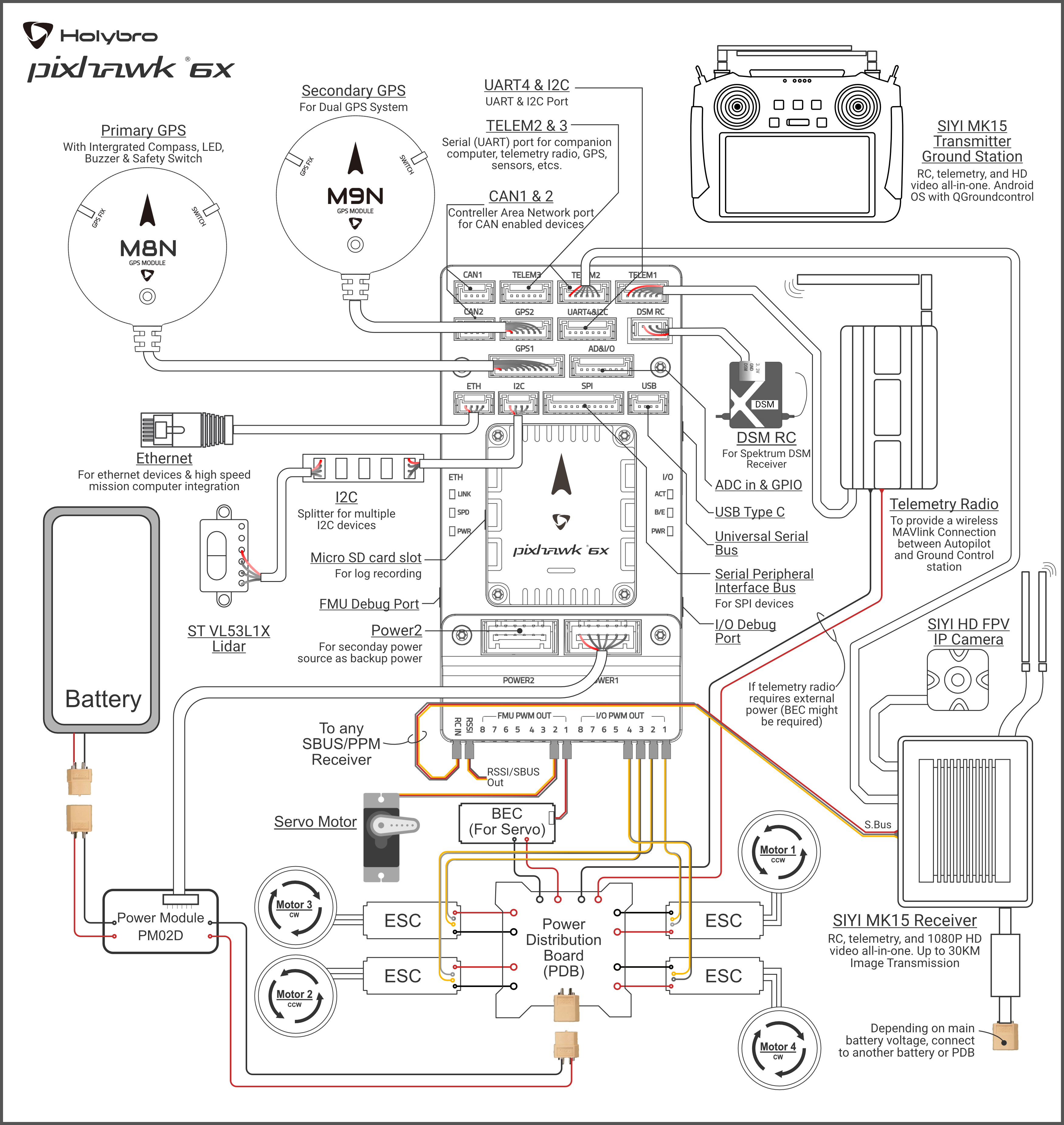
Note
duplicated RC control and telemetry solutions are shown. Duplicate systems are not usually used.
UART Mapping
SERIAL0 -> USB
SERIAL1 -> UART7 (Telem1) RTS/CTS pins
SERIAL2 -> UART5 (Telem2) RTS/CTS pins
SERIAL3 -> USART1 (GPS1)
SERIAL4 -> UART8 (GPS2)
SERIAL5 -> USART2 (Telem3) RTS/CTS pins
SERIAL6 -> UART4 (User)
SERIAL7 -> USART3 (Debug)
SERIAL8 -> USB (MAVLink, can be used for SLCAN with protocol change)
RC Input
The RCIN pin, which by default is mapped to a timer input, can be used for all ArduPilot supported receiver protocols, except CRSF/ELRS and SRXL2 which require a true UART connection. However, FPort, when connected in this manner, will only provide RC without telemetry.
To allow CRSF and embedded telemetry available in Fport, CRSF, and SRXL2 receivers, a full UART, such as SERIAL6 (UART4) would need to be used for receiver connections. Below are setups using Serial6.
SERIAL6_PROTOCOL should be set to “23”.
FPort would require SERIAL6_OPTIONS be set to “15”.
CRSF would require SERIAL6_OPTIONS be set to “0”.
SRXL2 would require SERIAL6_OPTIONS be set to “4” and connects only the TX pin.
Any UART can be used for RC system connections in ArduPilot also, and is compatible with all protocols except PPM. See Radio Control Systems for details.
PWM Output
The Pixhawk6X supports up to 16 PWM outputs. All 16 outputs support all normal PWM output formats. All FMU outputs, except 7 and 8, also support DShot.
The 8 FMU PWM outputs are in 4 groups:
Outputs 1, 2, 3 and 4 in group1
Outputs 5 and 6 in group2
Outputs 7 and 8 in group3
FMU outputs within the same group need to use the same output rate and protocol. If any output in a group uses DShot then all channels in that group need to use DShot.
Battery Monitoring
The board has 2 dedicated power monitor ports with a 6 pin connector. They are intended for use with the I2C power monitor supplied with the autopilot.
Note
do not try to use the Mission Planner SETUP->Optional Hardware->Battery Monitor tab to setup the I2C power monitors for the Pixhawk6X. The parameters needed for their operation are already setup by default:
BATT_MONITOR = 21
BATT_I2C_BUS = 1
BATT_I2C_ADDR = 65 (For Low voltage (6S) Digital Power Module),= 69 (For High Voltage (12S/14S) Digital Power Module)
Note
In Ardupilot 4.4 and later, the BATT_I2C_ADDR for Pixhawk 6X is default to be 0. This will perform an auto detection of the I2C address, and you do not need to change BATT_I2C_ADDR parameter.
Compass
The Pixhawk6X has a built-in compass. Due to potential interference, the autopilot is usually used with an external I2C compass as part of a GPS/Compass combination.
GPIOs
The 8 FMU outputs can be used as GPIOs (relays, buttons, RPM etc). To use them you need to set the output’s SERVOx_FUNCTION to -1. See GPIOs page for more information.
The numbering of the GPIOs for PIN variables in ArduPilot is:
FMU pins:
PWM1 50
PWM2 51
PWM3 52
PWM4 53
PWM5 54
PWM6 55
PWM7 56
PWM8 57
Additional GPIOs:
FMU_CAP1 58
NFC_GPIO 59
Analog inputs
The Pixhawk6X has 2 analog inputs, one 6V tolerant and one 3.3V tolerant
ADC Pin12 -> ADC 6.6V Sense
ADC Pin13 -> ADC 3.3V Sense
Analog 3.3V RSSI input pin = 103
Connectors
Unless noted otherwise all connectors are JST GH
Loading Firmware
The board comes pre-installed with an ArduPilot compatible bootloader, allowing the loading of xxxxxx.apj firmware files with any ArduPilot compatible ground station.
Firmware for these boards can be found here in sub-folders labeled “Pixhawk6X”.
Bi-Directional DShot firmware variations are available also.