Typical Autopilot Wiring Connections
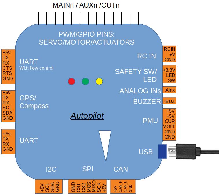
This topic covers the wiring/connection of basic/mandatory peripherals to the autopilot. For detailed explanations about each autopilot port/connector, see Autopilot Inputs and Outputs
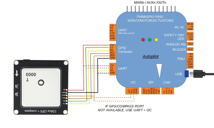
GPS/Compass
GPS is usually mandatory in plane,copter,and rover vehicles, except when some other position determining sensor or system is used. Sub does not use GPS. Compass is also usually required for Copter, Rover, Sub, and QuadPlane types of Plane (see Compass-less Operation for compass alternatives), but not for Conventional Planes, however it is recommended.
Note
Some Copter and Rover modes can operate without GPS and Compass (see vehicle documentation for its flight modes).
Multiple GPS and/or Compasses can be used in the system, see GPS Blending (aka Dual GPS), Advanced Compass Setup, and EKF3 Affinity and Lane Switching for more information
Note
TX and RX are swapped from autopilot to GPS module.
Note
Usually GPS is attached to the logical Serial Port 3 by default in ArduPilot. However, which physical UART is assigned to ArduPilot’s Serial Port 3 on the autopilot is documented in the autopilots documentation
Note
It is important that a GPS be connected to the first SERIALx port that has its SERIALx_PROTOCOL parameter set to “5” (GPS) since it will stop searching for GPS during boot-up if not found on the first port configured for GPS protocol.
As a wiring example, the topic 3DR UBlox GPS + Compass Module shows how to connect to a Pixhawk autopilot and includes additional configuration and mounting information.
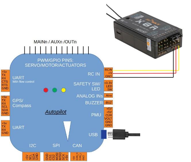
RC input
Note
Sub does not currently use RC control but it is under development.
Radio Control Receivers are normally used for pilot control. While exclusive pilot control via ground stations using telemetry is possible, it is not recommended. (However, it is possible to control the vehicle via ground station software using a joystick. See Joysticks.
ArduPilot autodetects the following serial RC receiver protocols:
PPM remote control (R/C) receivers
SBus receivers
FPort receivers (see FPort Receivers )
Crossfire (CRSF) and ELRS receivers (see Crossfire and ELRS RC Systems, needs full UART connection.)
Spektrum DSM and DSM2 receivers
Spektrum DSM-X Satellite receivers
IBUS receivers
MULTIPLEX SRXL version 1 and version 2 receivers.
For traditional single-wire-per-channel (PWM) receivers a PPM encoder can be used to convert the receiver outputs to PPM.
Tip
As of ArduPilot 4.0 versions of firmware, any autopilot UART may be used as an input for an RC receiver, instead of the designated RCin or SBUS input pin, by setting that port’s SERIALx_PROTOCOL to 23. However, some serial protocols require inversion (SBUS,FPort) and the UART must be capable of using the SERIALx_OPTIONS parameter to invert the RX input, otherwise, an external inverter will be required. This also allows a second RC receiver to be attached to the autopilot for redundancy. If the first receiver (first detected valid after boot) fails, then the second will be used. Note that whatever RC input ranges and trims were calibrated will be used for the second when it becomes active. Both receivers MUST be set to send no pulses in failsafe for this to work properly. RC_OPTIONS bit 10 must be set also.
Tip
Information about compatible receivers and how they are connected can be found in Radio Control Systems. Also see Multiple Radio Control Receivers for use of multiple RC receivers
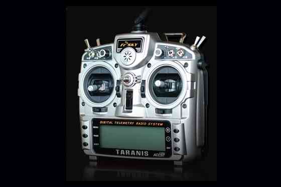
FRSky Taranis Transmitter
Motor/Servo Connections
Motor ESCs and/or PWM Servos are attached to the PWM outputs of the autopilot.
They are labeled either as MAIN/AUX outputs or just as OUTPUTs. These outputs provide the PWM or Dshot signals for motor ESC or servo control of flight surfaces. They can also be sometimes used as general purpose I/O pins for controlling relays, parachutes, grippers, etc.
Those controllers with MAIN/AUX output labels usually indicate that a IOMCU co-processor is being employed. These provide outputs intended for use as the motor/servo outputs and provide a redundant means of control via RC if the main autopilot fails. The MAIN outputs come from this co-processor, while the AUX designated outputs are controlled directly from the autopilot. Most board level autopilots do not use an IOMCU and have outputs only labeled OUTPUTx or Mx.
This distinction is important, since AUX outputs(and OUTPUTs from autopilots without an IOMCU) can be used as GPIOs as well as PWM or Dshot. While MAIN outputs can only be used for PWM.
Note
A few autopilots that do NOT use an IOMCU label their outputs as MAIN, so actually do have the capability of use as GPIOs and/or Dshot ESC control outputs. CUAV V5 Nano and Holybro Pixhawk 4 Mini are examples.
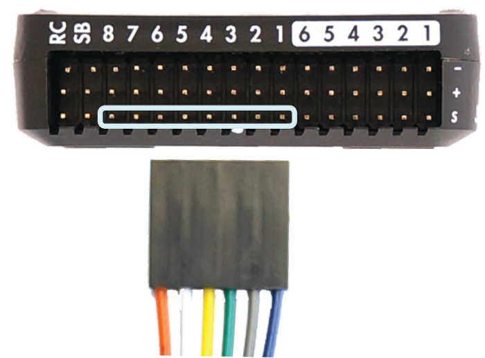
Often these outputs are provided on 3 pin connector strips supplying or distributing servo power and ground, in addition to the individual output signals. This power is usually provided externally, such as by the ESC or a BEC, although some autopilots provide this power from internal regulators.
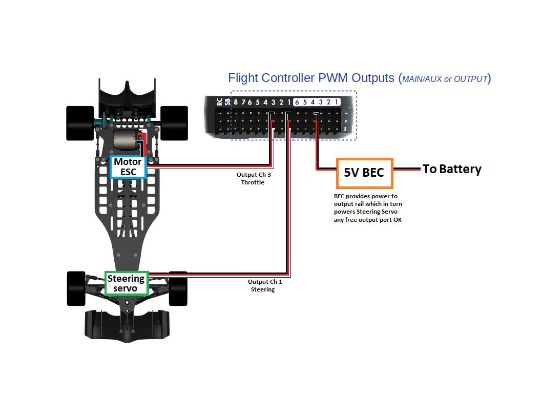
A connection example for Rover
An example for Copters using only motors. In this case, only ESC signal lines are being connected.
For Rovers connect the throttle and steering wires to the main output signal pins. The default settings are:
Output 3 = Throttle
Output 1 = Steering
The skid-steer output function parameters are used to configure vehicles that have fixed wheels and steer like tank tracks (ie. do not use servos to steer the wheels but rather use differential speed between the left and right wheels). The SERVOx_FUNCTION for the outputs used for each side’s motor are set using the Throttle Left and Throttle Right output functions. See Rover Motor Functions
Connect buzzer and safety switch
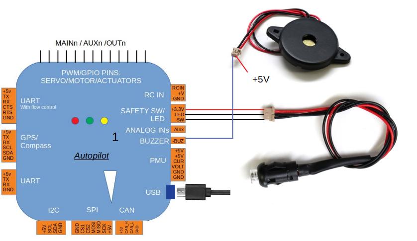
The buzzer and safety switch button are optional, but useful for some configurations. Not all autopilots provide these connections. A BUZZER and SWITCH can be connected to their respective ports as shown.
Warning
Mount the beeper at least 5cm away from the flight controller or the noise may upset the accelerometers.
Connect other peripherals
Depending on your hardware there may be any number of other peripherals attached, including sensors, cameras, grippers etc. These can be found as sub-pages of the topic Optional Hardware.
Information about connecting these peripherals to the autopilot is found in those respective pages.