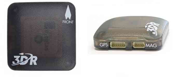
UBlox GPS + Compass Module
A UBlox GPS + Compass module is the most commonly used GPS for ArduPilot compatible autopilots. There are many versions of these modules available from various manufacturers, the recommended models are here.
ArduPilot automatically configures the GPS soon after startup so there is no need for any GPS related calibration. The compass must be calibrated however.
Connecting the Autopilot
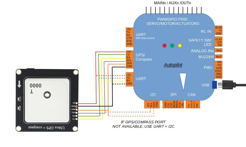
Example: Connecting to Pixhawk
Connect the GPS’s 6-pin DF13 connector to the Pixhawk’s “GPS” port and
the compass’s 4-pin connector to the I2C port. Alternatively the
compass can be first connected through an I2C splitter
if other I2C devices are to be attached.
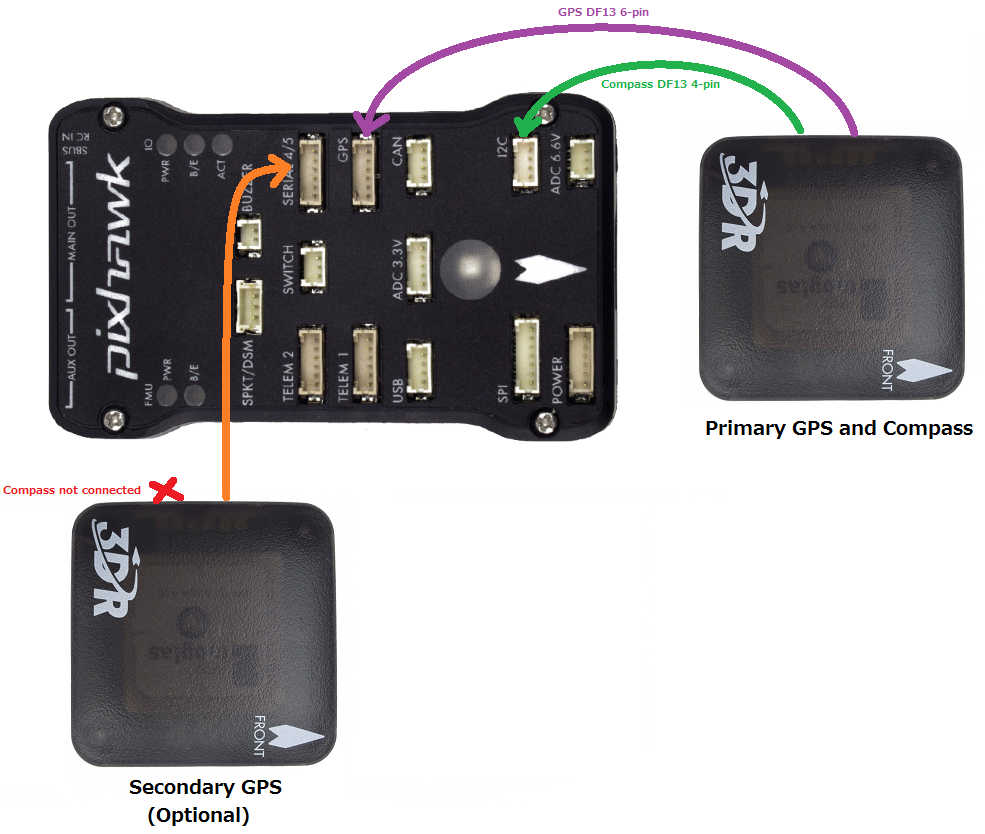
Details on how to setup and use a 2nd GPS can be found on the GPS Blending page page.
Note
The baud rate is set by the UBlox driver (setting SERIAL4_BAUD = 38 is ignored).
Note
ArduPilot supports many attached compasses, but only up to 3 compasses can be used during operation. See Advanced Compass Setup.
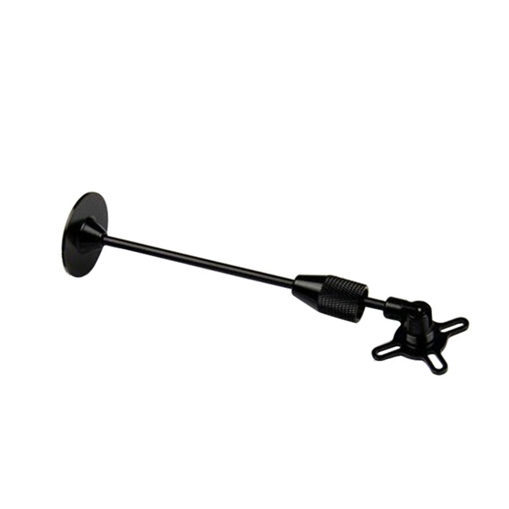
Mounting the GPS Module
This module permits the GPS to be mounted separately from the flight control module so that it can have the best clear (view) of the sky and allows the compass to be distanced from interfering magnetic fields.
Tip
The recommended orientation is to mount the module with the arrow facing toward the front of the vehicle and in the same direction as the arrow on the autopilot.
When mounting the GPS+Compass module:
Place the module on the outside of your vehicle (in an elevated position if appropriate) with a clear view of the sky, as far as possible from the motors and ESCs, with the arrow facing forward.
Distance the module from DC power wiring and the batteries by at least 10cm. Use of a GPS mast is highly recommended.
Place the module clear of nearby iron containing metallic objects. (Use nylon or non magnetic stainless steel hardware and nylon or aluminum standoffs to mount the module).
Twist power and ground wires where possible.
Setup in Mission Planner
Compass Calibration in Mission Planner explains the simplest way to calibrate a compass mounted in the recommended orientation (arrows for autopilot and compass facing to front of vehicle).
Advanced Compass Setup contains more detailed instructions for calibrating a compass if, for example, it has been mounted at some other orientation.
LED Indicators
The 3DR GPS+Compass module has two LED indicators: one for power (solid red) and one for GPS lock (flashing blue). Most GPS have an led indicator for 3D GPS lock acquisition.
LEDs: |
Behavior: |
Power |
Solid red when powered |
GPS lock |
Flashing blue when 3D GPS lock acquired |
Advanced Configuration
Advanced configuration of the UBlox GPS’s internal settings is documented in UBlox GPS Configuration. But this is never used by the average user. ArduPilot automatically configures the gps during initialization.