Tuning Process Instructions
Setting the aircraft up to be ready for tuning
The following parameters should be set correctly based on the specifications of your aircraft.
Step 1: Battery and expo settings
It is very important to ensure that the thrust curve of your VTOL motors is as linear as possible. A linear thrust curve means that changes in the actual thrust produced by a motor is directly proportional to the thrust being demanded by ArduPilot. If your thrust curve is badly non-linear then you will never produce a good tune, and in some cases may end up with such a bad tune that your vehicle can become completely unstable and crash.
There are 3 common causes of a non-linear thrust curve.
voltage sag as throttle is increased or the forward motor is engaged. This is very common in QuadPlanes
incorrect end-point setup in the PWM range you use to your ESCs (see “Motors setup” below)
non-linearity in the thrust produced by your propeller, ESC and motor combination
Start with setting up the voltage range to cope with voltage sag.
Q_M_BAT_IDX: index of the battery to use for voltage measurements on VTOL power system. Zero is the first battery, one for 2nd battery etc
Q_M_BAT_VOLT_MAX: 4.2v x No. Cells for LiPo
Q_M_BAT_VOLT_MIN: 3.3v x No. Cells for LiPo
Q_M_OPTIONS = 0 (default). The default is to use sag compensated voltage for the above and during tuning computations. It can be set to 1 to use raw voltage instead of sag compensated voltage, which may improve tuning results for light vehicles.
Note that Q_M_BAT_IDX needs to be for the correct battery for your VTOL motors. If you have a separate battery for forward motors and VTOL motors then make sure you use the right one.
Next setup the thrust expo. If you are setting up a professional aircraft then you should invest in a thrust stand so you can accurately measure the true thrust for your motor/ESC/propeller combination as you vary the throttle. Then you will adjust the expo value along with the endpoints (given by motors setup below) so that the thrust between the endpoints is as linear as possible. Do not trust manufacturer data for the thrust curve as they are frequently inaccurate. See Motor Thrust Scaling for details on thrust scaling.
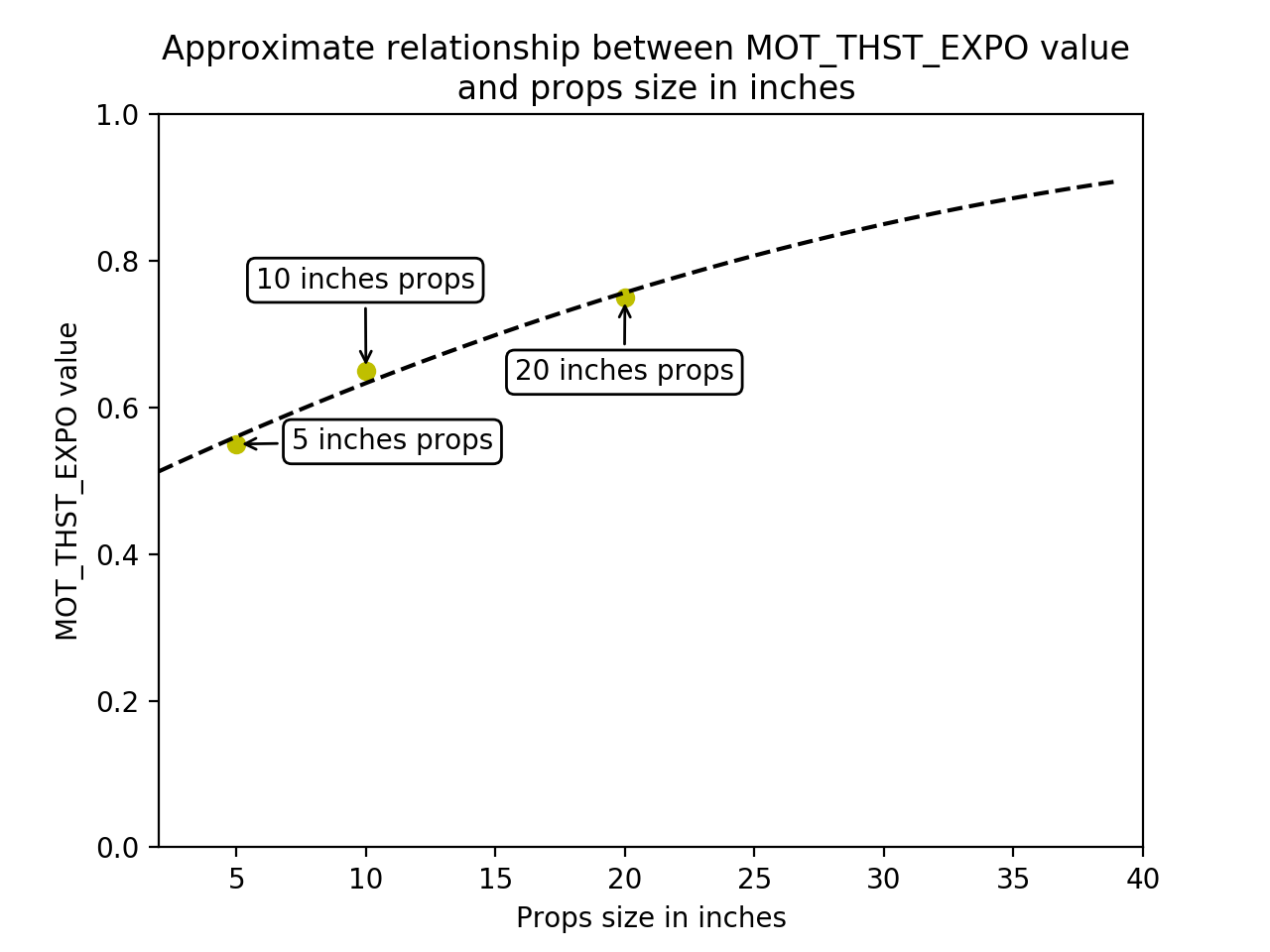
If you are setting up a hobby grade vehicle then you can use the graph below to estimate the correct Q_M_THST_EXPO value for your aircraft.
Q_M_THST_EXPO: 0.55 for 5 inch props, 0.65 for 10 inch props, 0.75 for 20 inch props.
Step 2: Motors setup
The motor parameters define the PWM output range sent to the ESCs. This is critical to ensure that the entire range of throttle values used in flight is within the linear range of your propulsion system.
For standard PWM based ESCs you should adjust Q_M_PWM_MIN until it is approximately 20 microseconds below the minimum value that causes the motors to just start spinning. If you are using digital motor outputs (such as DShot) then this is not necessary and the default of 1000 should be used.
You should then adjust Q_M_PWM_MAX to the value where the ESCs stop producing more thrust. Note that this is commonly a bit below the default maximum of 2000. To find the value you should test with propellers removed, and use the motor test facility of your GCS to find the lowest PWM value which produces the motors maximum RPM. You should be able to tell at what PWM the motors stop producing more thrust by listening to the sound made at different PWM values, or you can use a tachometer.
The Q_M_SPIN_MIN and Q_M_SPIN_MAX values are used to select a sub-range of the outputs to your motors which is linear. For hobby users the defaults are usually good, but for professional vehicles you should use the thrust stand data to determine the right range to produce linear thrust after the expo is applied.
Q_M_PWM_MAX: Check ESC manual for fixed range or 2000us
Q_M_PWM_MIN: Check ESC manual for fixed range or 1000us
Q_M_SPIN_ARM: use the motor test feature
Q_M_SPIN_MAX: 0.95
Q_M_SPIN_MIN: use the motor test feature
Q_M_THST_HOVER: 0.25, or below the expected hover thrust percentage (low is safe)
Step 3: PID Controller Initial Setup
The settings below are meant to get your PID controller acceleration and filter settings into the right approximate range for your vehicle. These parameters are critical to the tuning process.
INS_ACCEL_FILTER: 10Hz to 20Hz
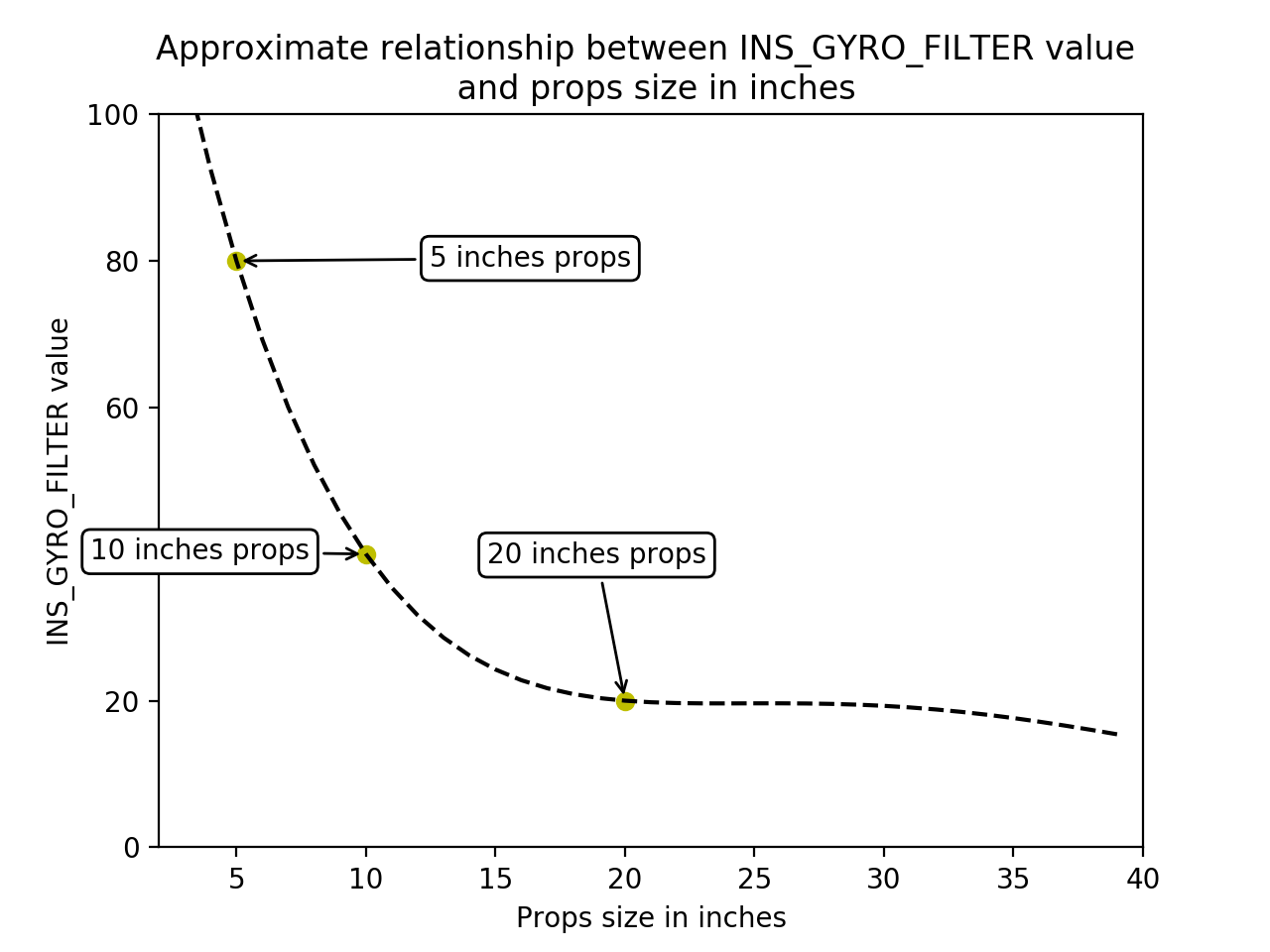
INS_GYRO_FILTER: 80Hz for 5 inch props, 40Hz for 10 inch props, 20Hz for 20 inch props
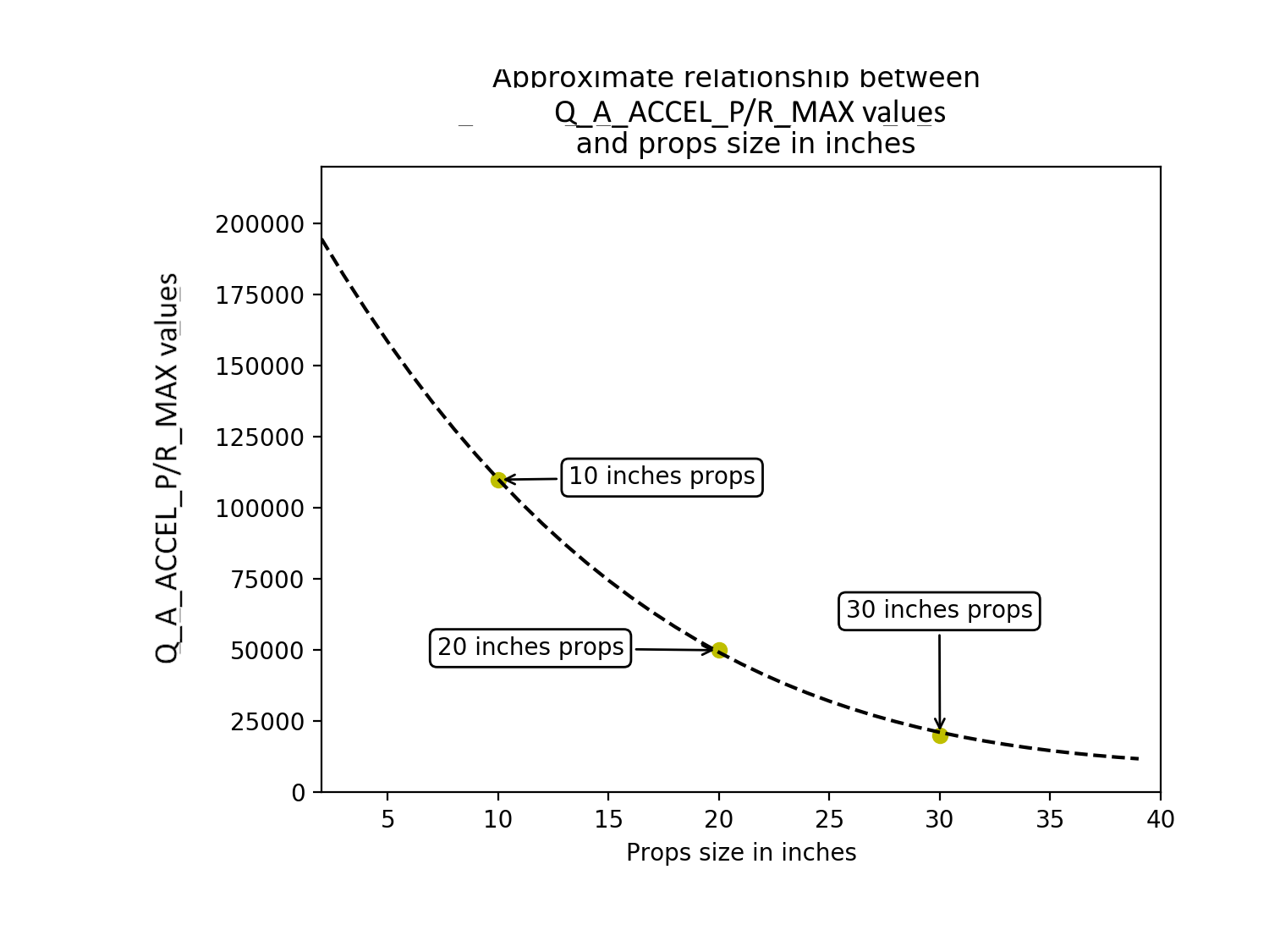
Q_A_ACC_P_MAX: 1100 for 10 inch props, 500 for 20 inch props, 200 for 30 inch props
Q_A_ACC_R_MAX: 1100 for 10 inch props, 500 for 20 inch props, 200 for 30 inch props
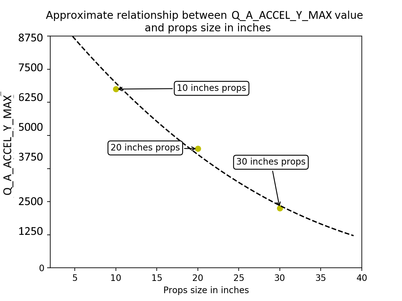
Q_A_ACC_Y_MAX: 75 for 6 inch props, 67.5 for 10 inch props, 45 for 20 inch props, 22.5 for 30 inch props
Q_A_RAT_YAW_P: 0.5 x Q_A_ACC_Y_MAX / 45
Q_A_RAT_YAW_FLTE: 0 for vectored yaw; 2.5 for other types of QuadPlanes
The initial tune of the aircraft should be done in the aircraft’s most agile configuration. This generally means that the aircraft will be at its minimum take off weight with fully charged batteries.
Step 4: Pilot’s preparation for first flight
The first takeoff of an untuned VTOL vehicle is the most dangerous seconds of the aircraft’s life. This is where the aircraft could be very unstable causing a sudden increase in power when then results in the aircraft jumping into the air, or it may be so poorly tuned that you have insufficient control over the aircraft once it is airborne. The pilot should be extremely diligent during the tuning flights to avoid a situation that could result in injury or damage.
There are several things that the pilot can do to minimize the risk during the early tuning process:
The pilot should conduct a motor number and orientation check (see Checking the motor numbering with the Mission Planner Motor test). Care should be taken to ensure that the correct frame type is selected. Incorrect frame type can result in a very fast yaw rotation or complete loss of control. Take note of the output percentage required to spin the propellers and ensure that:
Q_M_SPIN_ARM is set high enough to spin the motors cleanly.
Q_M_SPIN_MIN is set high enough to spin the motors with a minimal level of thrust.
All flights after a significant tuning change should be done in QSTABILIZE. QSTABIILIZE provides the pilot with significantly more control over the aircraft in the event that the attitude controllers are unstable.
The pilot should not take off in QHOVER until the altitude controller has been tested in flight. This should be done by taking off in QSTABILIZE and switching to QHOVER. Although QHOVER is rarely a problem unless the aircraft has a very low hover throttle.
For the initial flights the pilot should ensure that these parameters are set:
Q_A_THR_MIX_MAN to 0.1
Q_M_THST_HOVER to 0.25 (or lower than the expected hover throttle)
Use a radio and calibrate the radio correctly (see Radio Control Calibration).
Configure an ARM/DISARM switch and test it (see Auxiliary Functions).
Do tuning flights in low-wind condition and normal weather (no rain and between 15°C/59°F and 25°C/77°F).
Practice QSTABILIZE flight in simulator or on a low-end drone first. You should be confident to be able to takeoff and land with your untuned aircraft.
Tuning Process
Step 5: First Flight
The first take off is the most dangerous time for any QuadPlane. Care must be taken to ensure the aircraft is not destroyed in the first seconds of flight and nobody is injured.
Ensure that all spectators are at a safe distance.
Ensure the pilot is at a safe distance and position.
The pilot should refresh themselves on the method used to disarm the aircraft (using Auxiliary Functions for Motor Interlock or Arm/Disarm may be beneficial).
This flight will allow to setup your aircraft in a “flyable for tuning” state.
Ensure the aircraft is in QSTABILIZE mode
Arm the aircraft
Immediately disarm the aircraft to ensure your disarm procedure is correct
Arm the aircraft
Slowly increase the throttle looking for signs of oscillation. (long or flexible landing gear may cause some landing gear oscillation that will only go away after the aircraft leaves the ground)
As soon as the aircraft lifts off the ground immediately put the aircraft back down as gently as possible
Disarm the aircraft
Evaluate what you observed to decide if you need to make adjustments to the tuning parameters or if it is safe to take off again
Arm and increase the throttle to initiate a takeoff
Hover at approximately 1m altitude and apply small (5 degrees) control inputs into roll and pitch
Immediately land if any oscillation is observed
Next section will explain how to remove the oscillations.
Step 6: Initial aircraft tune
The first priority when tuning a QuadPlane is to establish a stable tune, free of oscillations, that can be used to do further tests.
Arm the aircraft in QSTABILIZE
Increase the throttle slowly until the aircraft leaves the ground
If the aircraft starts to oscillate immediately abort the takeoff and/or land the aircraft, and:
Reduce all the following parameters by 50%
This process is repeated until the aircraft can hover without oscillations being detectable visually or audibly.
If the aircraft has very long or flexible landing gear then you may need to leave the ground before ground resonance stops.
Be aware that in this state the aircraft may be very slow to respond to large control inputs and disturbances. The pilot should be extremely careful to put minimal stick inputs into the aircraft to avoid the possibility of a crash.
Step 7: Test QHOVER
This test will allow to test the altitude controller and ensure the stability of your aircraft.
Check Q_M_HOVER_LEARN is set to 2. This will allow the controller to learn by itself the correct hover value when flying.
Note
the Hover throttle value is only “learned” when the attitude is not being commanded by the pilot, or autopilot (ie QLOITER,etc.), to exceed 5 degrees from neutral for two seconds.
Take off in QSTABILIZE and increase altitude to 5m. Switch to QHOVER and be ready to switch back to QSTABILIZE. If the aircraft is hovering at a very low hover throttle value you may hear a reasonably fast oscillation in the motors. Ensure the aircraft has spent at least 30 seconds in hover to let the hover throttle parameter converge to the correct value. Land and disarm the aircraft.
Set these parameters on ground and preferably disarm (A confident pilot could set them in flight with GCS):
Q_P_D_ACC_I to 0.2 x Q_M_THST_HOVER
Q_P_D_ACC_P to 0.1 x Q_M_THST_HOVER
Note
In Plane 4.6 and earlier these parameters were named Q_P_ACCZ_I and Q_P_ACCZ_P and were scaled 10x larger:
Q_P_ACCZ_Ito 2 x Q_M_THST_HOVER
Q_P_ACCZ_Pto Q_M_THST_HOVER
If the QuadPlane in QHOVER starts to move up and down, the vertical position and velocity controllers may need to be reduced by 50%. These values are: Q_P_D_POS_P and Q_P_D_VEL_P.
Note
If the Q_M_THST_HOVER learned should be ~0.3-0.6. Higher values indicate that insufficient thrust is available, either due to motor system design, obstructed prop air flow by the fuselage or wings, or excessive yaw bias (see next section)
Step 8: Yaw Bias
A common problem in QuadPlanes is excessive amount of VTOL power being used to maintain yaw hold instead of providing lift. This can be caused by:
small misalignment of the VTOL motors
frame twist (often caused by wing twist) as thrust is applied
obstructed prop air flow by wings in TVBS type tailsitters making vectored yaw by motor tilt less effective. This can also cause enough reduction in normal thrust to make hovering and VTOL climb difficult.
If too much power is needed to maintain yaw then the aircraft could lose yaw control during transitions, or could lose roll and pitch stability. The most common symptom is a high hover throttle point, or even the inability to rise into a hover at high throttle stick position. For larger QuadPlanes it is common to need to deliberately tilt the motors by a couple of degrees to increase yaw authority.
Note
for an X frame type (Q_FRAME_TYPE = 1), the motors should be tilted outwards. For an H frame (Q_FRAME_TYPE = 3) they should be tilted inwards.
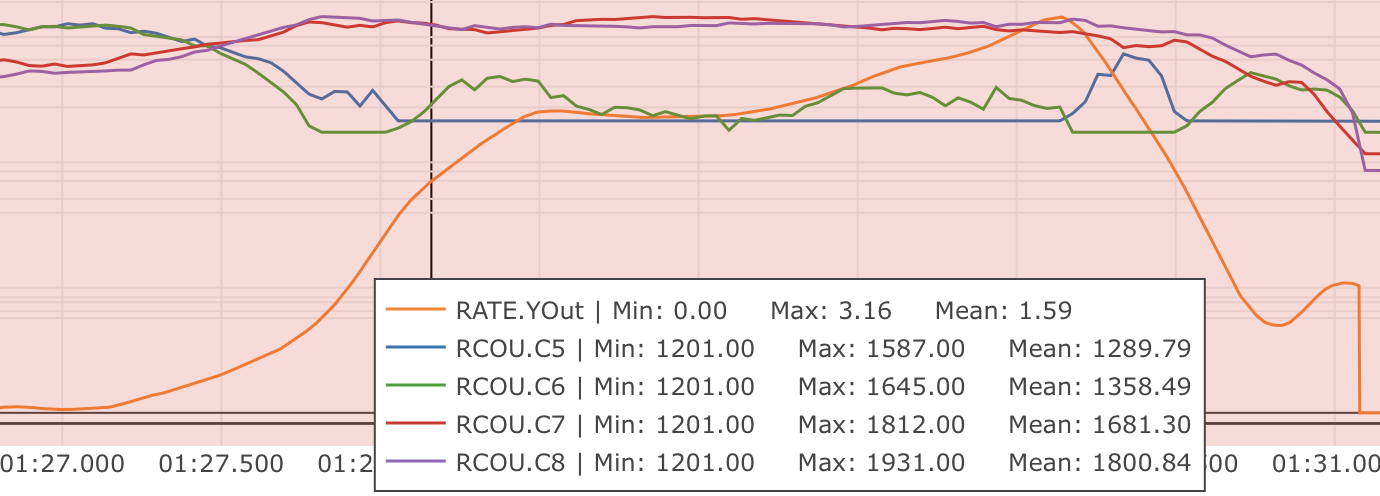
You should check the amount of thrust being used to maintain yaw by looking at the RATE YOut value in your hover logs. If it is over 10% (a value of 0.1) when hovering in no wind with no pilot input,then you have a problem with yaw asymmetry that should be fixed. Just hovering in place may look fine and you may not see the problem until you examine the log.
The log below shows RATE.YOut (orange) increasing dramatically while motor 1 (RCOUT.C5) is idling and motor 2 (RCOUT.C6) is barely working, but at the same time motor 3 (RCOUT.C7) and motor 4 (RCOUT.C8) are are running > 50% output. This limits how much higher the firmware could raise the overall thrust due to these motors maxing out.
Fixing yaw asymmetry can involve mechanical improvements such as stiffening the airframe to resist twisting, making sure prop flow is unobstructed by the wings on TVBS frames,or correcting/adjusting motor tilt angles
Some QuadPlanes will benefit from being setup as H frames instead of X frames. Which works best depends on the way the motor mounts twist when under thrust. If you have a persistent problem with yaw control then consider trying to change the frame type between X and H, however a quadplane with motors mounted on booms secured to the wings would normally be setup as an X frame.
Step 9: Notch Filtering
After your have QHOVER flying without oscillations the next step is to get get a good notch filter setup to reduce noise to the VTOL PID controllers. A good set of notch filtering parameters is critical to a good tune.
To get a notch filter setup you need to hover your QuadPlane for 2 minutes with no pilot input and with INS_LOG_BAT_MASK set to 1. This will enable FFT logging which will guide the correct setup of the notch filters. You should then carefully read the Managing Gyro Noise with the Dynamic Harmonic Notch Filters documentation and setup a harmonic notch to remove the noise from your gyros.
When setting up your filtering you should consider the cause of any oscillation you find. On most aircraft the vibrations you find will be directly caused by a multiple of the RPM, but on some aircraft a frame resonance or resonance in the autopilot mount may be the cause. Understanding the cause of any resonances is critical to reducing noise enough to get a good tune.
Step 10: Manual tuning of Roll and Pitch
While you may be tempted to jump straight to autotuning, this is not recommended. Most QuadPlanes need some manual tuning of roll and pitch before they can handle an autotune. If you jump straight to an autotune then your aircraft may become unstable enough to crash. A good manual tune will also reduce the amount of time an autotune will take, which can be critical given the small VTOL hover times of many QuadPlanes.
Before starting the manual tune you should go back and check you have fully completed the steps above, and ensure you have a good notch filter setup to remove noise from the gyros.
Hover the aircraft in QSTABILIZE or QHOVER modes, in low wind, with good sky view and good GPS lock. You should adjust the rate gains as described below, using small “twitches” on the sticks after each change to try to trigger oscillation.
If oscillations start do not make large or sudden stick inputs. Reduce the throttle smoothly to land the aircraft while using very slow and small roll and pitch inputs to control the aircraft position.
The parameters you will be adjusting are:
Note
If the VTOL motors do not tilt, then the Q_A_RAT_PIT_FF and Q_A_RAT_YAW_FF will be zero and corrections are dominated by P/I/D. But if pitch or yaw control is primarily by tilting the motors, then the FF terms dominate and P/D are primarily for disturbance correction. For tuning a tilted motor controlled axis, see Pitch and Yaw Tuning.
Start with the roll parameters, then move onto the pitch.
Increase the D term in steps of 50% until oscillation is observed
Reduce the D term in steps of 10% until the oscillation disappears
Reduce the D term by a further 25%
Increase the P term in steps of 50% until oscillation is observed
Reduce the P term in steps of 10% until the oscillation disappears
Reduce the P term by a further 25%
Each time the P term is changed in the above steps you should set the corresponding I term equal to the P term. Those parameters can be changed on ground and preferably disarmed. Alternatively, a confident pilot could set them in flight with a GCS, or use the transmitter tuning option. See Transmitter Based Tuning
Note that it is common that once you have properly setup notch filtering that you will be able to increase the D value a lot from the default value. Increases of 10x over the default are not uncommon. Being able to use a larger D gain is one of the main advantages of good notch filtering, and can produce a much better tune.
After you have gone through the above steps you should carefully look at your logs to ensure you don’t have a hidden oscillation. The structure of QuadPlanes sometimes means that oscillations may not be externally visible. You should use the RATE, PIQR and PIQP messages to look for oscillations.
Step 11: Evaluating the aircraft tune
You need to evaluate the aircraft’s tune to see if the previous steps have resulted in a tune which is good enough for a transition flight or for autotuning.
Take off in QHOVER or QSTABILIZE
Apply small roll and pitch inputs. Start with 5 degree inputs and releasing the stick to centre, pitch, left, right, roll forward back, then all 4 points on the diagonal
Increase inputs gradually to full stick deflection
Go to full stick deflection, quickly momentarily, and let the sticks spring back to centre
If the aircraft begins to overshoot significantly or oscillate after the stick input, halt the tests before the situation begins to endanger the aircraft. The aircraft may require more manual tuning before autotuning can be run.
To test the stabilization loops independent of the input shaping, set the parameter: Q_A_RATE_FF_ENAB to 0.
Take off in QHOVER or QSTABILIZE
Hold a roll or pitch input
Release the stick and observe the overshoot as the aircraft levels itself
Gradually increase the stick deflection to 100%
Halt the tests if the aircraft overshoots level significantly or if the aircraft oscillates and go back to manual tuning.
Set Q_A_RATE_FF_ENAB to 1 after the tests are complete.
Step 12: Autotuning
Often, the default params or a good manual tune will be sufficient. However, autotuning can usually improve the tune.
If the aircraft appears stable enough to attempt autotuning and you have sufficient battery to last through an autotuning session then you can autotune using one of two methods:
QAUTOTUNE Mode (no longer the recommended method, and is not compiled into most firmware).
Using the Quick VTOL Tune LUA Applet to Automate Tuning
Note
As of ArduPlane 4.6, this is now integrated into the firmware as code, directly.
For systems using an autopilot with sufficient memory to run LUA scripts, such as F7 and H7 based controllers, this process has been automated via a LUA Applet.
Be sure that scripting has been setup and sufficient memory has been allocated, as explained in LUA scripts.
See the Quick VTOL Tune LUA script.
Using the QAUTOTUNE mode to Automate Tuning
Follow the instructions in the QAUTOTUNE page.
You should use QAUTOTUNE on one axis at a time (setting Q_AUTOTUNE_AXES for the axis you want to tune). An autotune of a single axis will typically take 5 to 8 minutes, but will take longer if your manual tune is not good enough. If you do not have enough battery for at least 8 minutes of vertical flight then QAUTOTUNE is not recommended.
There a number of problems that can prevent QAUTOTUNE from providing a good tune. Some of the reason QAUTOTUNE can fail are:
High levels of gyro noise.
Incorrect value of Q_M_THST_EXPO.
Flexible frame or payload mount.
Overly flexible vibration isolation mount.
Non-linear ESC response.
Very low setting for Q_M_SPIN_MIN.
Overloaded propellers or motors.
Autotuning a Tailsitter’s pitch or yaw axis, or vectored yaw axis on TiltRotor, since they require feed-forward.
If QAUTOTUNE has failed you will need to re-do a manual tune.
Some signs that QAUTOTUNE has been successful are:
An increase in the values of Q_A_ANG_PIT_P and Q_A_ANG_RLL_P.
Q_A_RAT_PIT_D and Q_A_RAT_RLL_D are larger than Q_AUTOTUNE_MIN_D.
QAUTOTUNE will attempt to tune each axis as tight as the aircraft can tolerate. In some aircraft this can be unnecessarily responsive. A guide for most aircraft:
Q_A_ANG_PIT_P should be reduced from 10 to 6
Q_A_ANG_RLL_P should be reduced from 10 to 6
Q_A_ANG_YAW_P should be reduced from 10 to 6
Q_A_RAT_YAW_P should be reduced from 1 to 0.5
Q_A_RAT_YAW_I: Q_A_RAT_YAW_P x 0.1
These values should only be changed if QAUTOTUNE produces higher values. Small aerobatic aircraft may prefer to keep these values as high as possible.
Step 13: Setting the input shaping parameters
QuadPlane has a set of parameters that define the way the aircraft feels to fly. This allows the aircraft to be set up with a very aggressive tune but still feel like a very docile and friendly aircraft to fly.
The most important of these parameters is:
Q_A_RAT_YAW_P: yaw rate x 45 degrees/s
Q_A_ANGLE_MAX: maximum lean angle
Q_A_ACC_P_MAX: Pitch rate acceleration
Q_A_ACC_R_MAX: Roll rate acceleration
Q_A_ACC_Y_MAX: Yaw rate acceleration
Q_A_ANG_LIM_TC: Aircraft smoothing time
QAUTOTUNE mode tuning will set the Q_A_ACC_P_MAX, Q_A_ACC_R_MAX and Q_A_ACC_Y_MAX parameters to their maximum based on measurements done during the QAUTOTUNE tests. These values should not be increased beyond what QAUTOTUNE suggests without careful testing. In most cases pilots will want to reduce these values significantly.
The Quick VTOL Tune LUA Applet will not adjust these from defaults and you may adjust them to get the feel you desire.
For aircraft designed to carry large directly mounted payloads, the maximum values of Q_A_ACC_P_MAX, Q_A_ACC_R_MAX and Q_A_ACC_Y_MAX should be reduced based on the minimum and maximum takeoff weight (TOW):
Q_A_ACC_P_MAX x (min_TOW / max_TOW)
Q_A_ACC_R_MAX x (min_TOW / max_TOW)
Q_A_ACC_Y_MAX x (min_TOW / max_TOW)
Q_A_RAT_YAW_P should be set to be approximately 0.5 x Q_A_ACC_Y_MAX / 4500 to ensure that the aircraft can achieve full yaw rate in approximately half a second.
Q_A_ANG_LIM_TC may be increased to provide a very smooth feeling on the sticks at the expense of a slower reaction time.
Aerobatic aircraft should keep the Q_A_ACC_P_MAX, Q_A_ACC_R_MAX and Q_A_ACC_Y_MAX provided by QAUTOTUNE and reduce Q_A_ANG_LIM_TC to achieve the stick feel desired by the pilot.
The full list of input shaping parameters are: