Gimbal / Mount Controls
ArduPilot provides mechanisms to control the pointing direction (aka targeting) automatically for camera mounts (know hereafter as mounts), as well as by pilot commands/controls. Mounts can be commanded point in at least six different ways (targeting modes) by ArduPilot. This page provides an overview of these controls and their setup.
Note
The Mount feature and individual gimbal drivers are NOT normally included on standard firmware for smaller flash (F4) boards. Use the Custom Firmware Build Server to create firmware that includes it.
Note
ArduPilot supports up to two mounts. Each mount has parameters associated with it, e.g. MNT1_TYPE, MNT2_TYPE, MNT1_RC_RATE, MNT2_RC_RATE, etc. For the remainder of the article, we will use MNT1 for examples of setups and parameters.
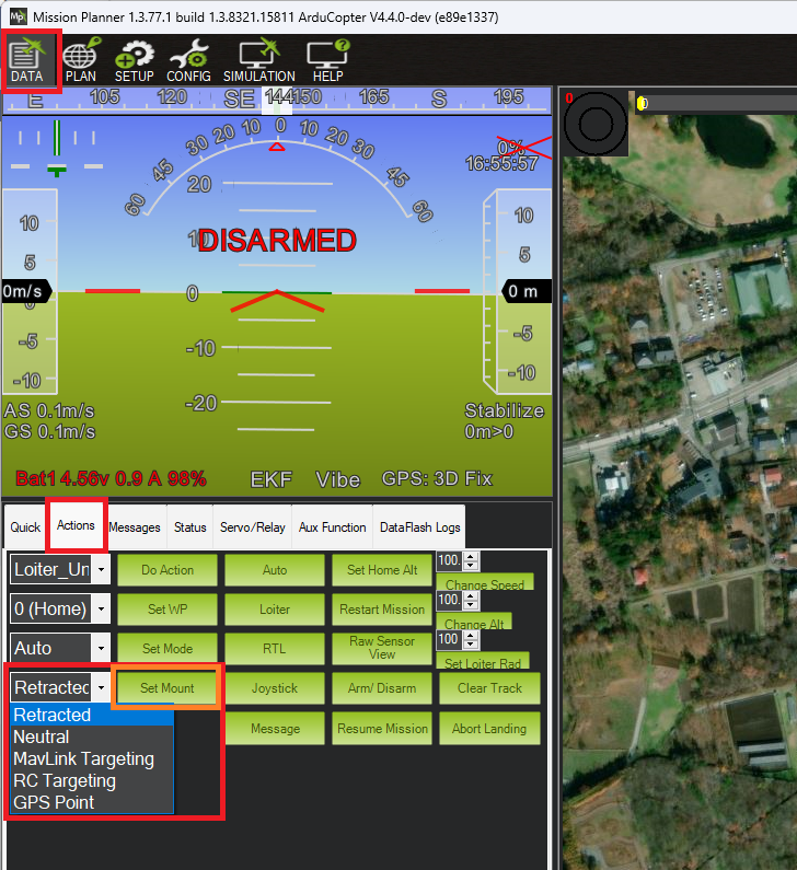
The mount’s “targeting mode” defines how it is controlled. Each ground station (GCS) is different but Mission Planner, for example, has a “Set Mount” button that allows changing the mode. In many cases the user does not need to directly set the mode, instead this is done automatically as part of responding to a command from the user.
In order to enable the mount, a MNT1_TYPE must be selected corresponding to the mount type. This will allow its mount parameters to be seen.
Targeting Modes
Below are the 6 supported targeting modes.
Retract Mode: the mount will move to the roll, pitch and yaw angles held in the MNT1_RETRACT_X, MNT1_RETRACT_Y, MNT1_RETRACT_Z parameters respectively. Some special mount specific behaviours:
Gremsy mounts will immediately stop stabilising
Servo mount will move to the specified angles and stop stabilising.
Siyi mounts do not provide roll control so the roll angle (MNT1_RETRACT_X) is ignored.
If a servo has been setup to mechanically deploy/retract the mount (
SERVOx_FUNCTION= 9 for MNT1, “15” for MNT2) it will be commanded to retract the mount. Changing to another mode will command the servo to deploy the mount.
Neutral Mode: the mount will move to the roll, pitch and yaw angles held in the MNT1_NEUTRAL_X, MNT1_NEUTRAL_Y, MNT1_NEUTRAL_Z, respectively.
MAVLink Targeting: the mount will move according to real-time commands received from the ground stations, companion computers or other MAVLink command source, and/or Auto mode mission commands. See MAV_CMD_DO_GIMBAL_MANAGER_PITCHYAW.
RC Targeting: the pilot controls the mount in real-time using the RC transmitter. See section below for more information.
GPS Point: same as MAVLink targeting but ArduPilot forces the mount to point at a specific location. Users never need to actively set the mount to this mode. The user usually selects a point and altitude on the GCS map and selects a right click menu item to “Point the camera here”.
SysId Target: the mount points at another vehicle with the MAVLink system id specified. Users never need to actively set the mount to this mode and there are no known GCSs that support setting the system id, but the parameter can be set by updating the value of MNT1_SYSID_DFLT directly.
Home Location: the mount points at Home (normally its location when armed, unless changed by the user in the GCS)
The mount’s default mode on startup can be set with the MNT1_DEFLT_MODE parameter.
Note
ArduPilot 4.5 (and higher) automatically switches the mount to RC Targeting Mode if the pilot moves any configured Roll/Pitch/Yaw RC targeting inputs (see below) by the larger of 10uS or RCx_DZ. The only exception is if the mounts is in RETRACT mode in which case the mount mode will not be automatically changed.
Mount Internal Axis Locks
The above modes concern how pitch, roll, and yaw axis TARGETs are sent to the mount. But many mounts have internal controls for how those targets for pitch, roll, and yaw are interpreted. Those positioning commands can be interpreted by the mount as being with respect to Earth frame reference or Body frame. Body frame are angle targets on each axis measured with respect to the mount itself, while Earth frame is interpreted to be with respect the horizon and compass heading.
For example, at 30 deg negative pitch target would be 30 deg down from the mount’s zero point with respect to its mounting in Body frame, but 30 deg below the earth’s horizon in Earth frame.
Most mounts have internal controls for each axis to determine how to interpret the targets. ArduPilot sets the mount’s pitch and roll axis frame (if configurable) to Earth frame interpretations for all Mount types via its driver.
The yaw axis is forced to Earth frame for the GPS Point, Home, and SysID modes, and is otherwise body frame controlled.
Mount RC failsafe position
In the event of an RC failsafe, the mount can be moved to the Neutral mode position if the MNTx_OPTIONS bit 1 is set.
Control with an RC transmitter (aka RC Targeting)
While the mount is in “RC Targeting” mode (see above for how to change modes), the pilot can control the mount’s target roll, pitch and yaw angles using an RC transmitter channel for each axis. For example (RC channels shown are for example only, and can be any channel not otherwise used):
set RC6_OPTION = 212 (“Mount1 Roll”) to control the mount’s roll angle with RC channel 6
set RC7_OPTION = 213 (“Mount1 Pitch”) to control the mount’s pitch angle with RC channel 7
set RC8_OPTION = 214 (“Mount1 Yaw”) to control the mount’s yaw angle with RC channel 8
ensure the RCx_TRIM parameter for each RC input channel used is half way between RCx_MIN and RCx_MAX
Note
By default the RC input specifies the angle but this can be changed to rate control by setting MNT1_RC_RATE to a non-zero desired rotation rate in deg/sec.
The pilot can retract the mount with the “Retract Mount1” or “Retract Mount2” auxiliary switch (using RC 10 in the below example.)
RC10_OPTION = 27 (“Retract Mount1”) to change the mount to Retract mode
RC10_OPTION = 113 (“Retract Mount2”) to change the mount to Retract mode
Axis Lock Auxiliary Switches and Options
If the mount is capable, the roll and pitch axes can be controlled in the RC Targeting mode with an auxiliary switch on an RC channel, if you use ANGLE, not RATE controls (eg. MNT1_RC_RATE = 0. In the future this will be expanded to RATE control also). For example using RC channel 9, set RC9_OPTION = 185 to enable this switch. Switching its position will force roll and/or pitch angles of the mount to be stabilized (‘locked”) in earth frame (ie with respect to the horizon) or body frame (with respect to the gimbals base)
AUX FUNC |
Roll |
Pitch |
Name |
Description |
|---|---|---|---|---|
High |
Earth Frame |
Earth Frame |
HORIZON |
Gimbal’s pilot-set roll and pitch angles stabilized with respect to the horizon. Horizon does not move in video. |
Middle |
Body Frame |
Earth Frame |
PITCH |
Like HORIZON but vehicle banks are seen in video. |
Low |
Body Frame |
Body Frame |
FPV |
Gimbal angles maintained with respect to its base. This is good for FPV flying since horizon moves normally with respect to vehicle attitude. |
Note
Currently only the CADDX, Storm32, SimpleBGC, Brushless, and Servo type mounts have the above capability.
Note
If the Aux switch above is not used, HORIZON mode is the normal mode of gimbal operation
MOUNTx_OPTIONbit 3 (+4 in value) provides the ability to obtain FPV lock above (on gimbals that are capable), without the need for the switch,Also in RC Targeting, an Auxiliary Switch function “163” (Mount Yaw Lock) can be used on an RC channel to switch from normal yaw operation, to capturing the heading that the gimbal is currently pointing and “locking” it to maintain that direction. RC yaw target controls can shift that heading point. Switching it low, or changing mount modes, returns normal operation.
POI(aka ROI) Auxiliary Function
If Terrain is enabled and data available, you can lock the gimbal target to a POI that it is pointing at and track it with the gimbal as the vehicle moves using a transmitter Aux Function switch (eg. RC10_OPTION = “186”) or via GCS Aux Function activation. The AUX FUNC values:
AUX FUNC |
Description |
|---|---|
High |
The ground location that the gimbal is pointing at is recorded (POI location) if it is currently clear and gimbal is switched to GPS Point targeting mode. The gimbal’s entry mode is recorded also. If the POI location has already been recorded, then the mode is just switched back to GPS Point to track the POI target. |
Middle |
If the POI location is set, then gimbal mode is reverted to the above saved mode to allow navigation, etc. but POI location is retained. Otherwise, no action. |
Low |
POI location is cleared and gimbal targeting mode set to its default mode (eg. MNT1_DEFLT_MODE) |
Warning
in order for this to be accurate, the mount’s MNT1_PITCH_MAX, MNT1_PITCH_MIN, MNT1_YAW_MAX, and MNT1_YAW_MIN must accurately reflect the gimbal’s EARTH FRAME angle extremes while in the vehicle’s normal attitude when function is activated (usually Plane in cruise, Copter in hover, etc.)
POI Altitude
If Terrain data is enabled and available, the gimbal’s “boresight” POI will be set to whatever terrain elevation it is pointing. If not, the HOME altitude will be used for the POI point.
Mission Planner Mount Controls
Mission Planner uses MAVLink commands to control the mount. The mount’s angles can be controlled as follows
Set the mode to “MAVLink Targeting” using the Data screen’s Actions tab’s bottom left drop-down and then push the “Set Mount” button (see image above)
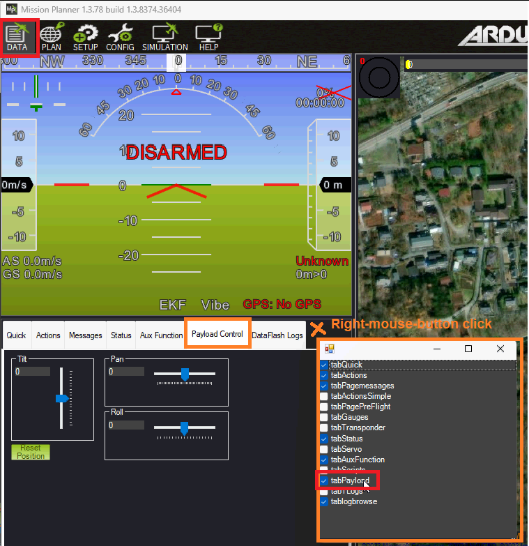
Use the Payload Control tab to adjust the mount’s roll, pitch or yaw angles
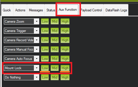
Use the Aux Function tab to switch the yaw between “follow” and “lock” modes
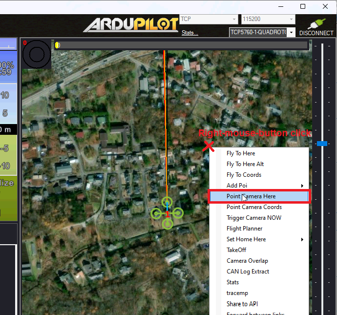
To point the mount at a particular location (e.g. lat, lon, alt), on the Data screen, right-mouse-button click on the map and select, “Point Camera Here” and enter an altitude above home
QGC Mount Controls
QGC-4.4 (and higher) supports controlling the mount from a Toolbar or by directly clicking on the real-time video. The vehicle must be using ArduPilot 4.5 (or higher)
The mount control toolbar should appear at the top once a mount is detected. Click on the toolbar to display the mount control buttons
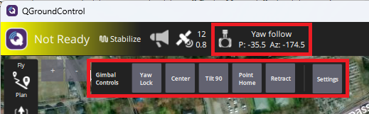
“Yaw Lock” / “Yaw Follow” controls whether the mount maintains an earth-frame yaw target (aka “lock”) or moves with the vehicle’s yaw (aka “follow”)
“Center” centers the mount (or more precisely moves it to the roll, pitch and yaw angles held in MNT1_NEUTRAL_X, MNT1_NEUTRAL_Y, MNT1_NEUTRAL_Z)
“Tilt 90” points the mount directly downwards
“Point Home” points the mount at the home location
“Retract” retracts the mount (or more precisely moves it to the roll, pitch and yaw angles held in MNT1_RETRACT_X, MNT1_RETRACT_Y, MNT1_RETRACT_Z)
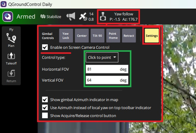
The mount may also be controlled by clicking on the real-time video screen
Push the “Setting” button
Check “Enable on Screen Camera Control” and set “Control type” to “Click to point”
Enter the camera’s Horizontal FOV and Vertical FOV
Maximise the real-time video and click anywhere on the screen and the mount should move appropriately
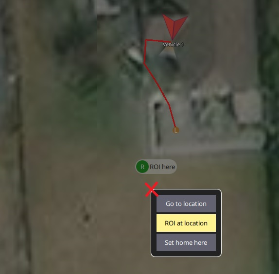
To point the mount at a Location
While the vehicle is flying, maximise the map
Click anywhere on the map and select “ROI at location”
To stop pointing at the location, click on the “ROI here” icon and select “Cancel ROI”. The mount will return to the mode held in the MNT1_DEFLT_MODE parameter
Companion Computer mount Controls
MAVLink mount commands can also be sent from other sources, such as companion computers. See Control a Gimbal / Camera Mount for a commands list and more information.
Cameras may also be controlled via MAVLink commands from a companion computer or other source. See Control a Camera documentation.
Control during Auto mode missions
Commands to control the mount are listed on the Camera Control in Auto Missions, Copter Mission Command List and Mission Commands pages
Other Mount Parameters
MNT1_ROLL_MAX and MNT1_ROLL_MIN control the mount’s roll axis movement range in degrees
MNT1_PITCH_MAX and MNT1_PITCH_MIN control the mount’s pitch axis movement range in degrees
MNT1_YAW_MAX and MNT1_YAW_MIN control the mount’s yaw axis movement range in degrees
MNT1_OPTIONS bit 0 set will recover the yaw lock state of the previous mode. For example if the mount’s yaw lock was body frame in RC Targeting mode and the mount mode switched to GPS Point (which forces earth frame yaw) and then switched back to RC Targeting, the yaw would be still earth frame unless this bit is set. Bit 1 set will force Neutral mode in RC failsafe to possibly re-center the camera in failsafe when user control has been lost. Bit 2 , in RC Targeting mode, force the roll and pitch axes to lock to the gimbal’s body frame for FPV operation (ie horizon moves with vehicle roll and pitch in camera view)
Warning
For MAVLink controlled mounts,the mount supplies its axes max and min angles. The user can override these to limit the gimbal, but this alters the defaults for those parameters and using a different MAVLink gimbal will NOT use its communicated limits unless the entire autopilot parameters are reset.