Configuring a Telemetry Radio using Mission Planner
This article explains how to configure Telemetry Radios using Mission Planner.
Tip
Many users will not need to configure their radios! One case where you might do so is when you use your vehicle with others — in which case you will need to specify different radio channels (Net ID).
Overview
Mission Planner supports configuring your radios using a simple GUI interface.
To make changes:
Connect one of the radios to your computer using the micro USB cable.
Power the radio attached to the vehicle by plugging in the vehicle’s battery.
Open the Mission Planner and go to the Initial Setup | Optional Hardware | SiK Radio page.
Select the correct COM port and set the baud rate to 57600. Ensure the “Connect” button is in a disconnected state as shown in the image below..
Press the Load Settings button and both the Local and Remote areas should fill in with values including the firmware Version
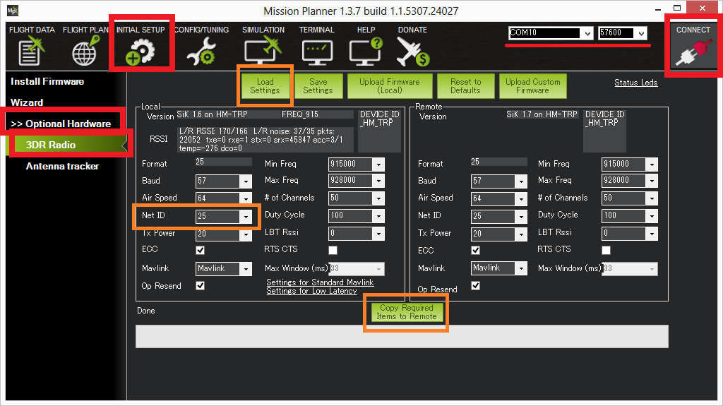
The most common entry to change is the
Net ID. The default is 25 for most radios but if you plan to fly in an area with other pilots who may be using the same radio it is best to change this to another number.After making changes, click the Copy Required Items to Remote and press Save Settings
Other parameters you may choose to update:
Baud (default 57) : the rate at which the mission planner or vehicle communicates with the local radio. “57” = 57600 bits per second.
Air Speed (default 64) : the rate at which the two radios will communicate with each other. “64” = 64kbps (kilobits per second). Setting a lower rate will increase the range of the radio but reduce the rate of data (i.e. the amount of data that can be sent in a given time) across the link.
ECC (default is “on”): controls whether error correction is on or off. When on “12/24 Golay error correcting code” is used which involves sending a 16 bit CRC byte along with the data to ensure that bad data is thrown away. Unfortunately this also halves the data rate across the link but it is recommended to leave ECC on especially when when the vehicle is far from home base because transmission errors increase greatly with distance.
MAVlink (default is “MAVLink”) : this controls whether the transmission is optimised for MAVLink packets or not. Set to “Low Latency” if using a joystick or an android tablet’s virtual joystick to manually fly the vehicle. Note that information on the radio signal strength (rssi) and error rate is only sent if this parameter is set to its default, “MAVLink”.
Tx Power (default 20) : the transmission power where 1=1.3milliWats, 2=1.5mW, 5=3.2mW, 8=6.3mW,11=12.5mW, 14=25mW, 17=50mW, 20=100mW. This should be set to conform with your local regulations. Some per-country information is linked here.
Duty Cycle (default 100) : the maximum percentage of time that the radio will transmit packets. Some regions of the world allow for higher transmit power or more frequencies if you have a duty cycle below a given threshold. So for example in Europe you can transmit on a wider range of frequencies in the 433 band if your duty cycle is below 10%. Telemetry traffic is quite ‘bursty’, so the average transmit time is not generally high. When you set a duty cycle below 100% then your available bandwidth will be reduced, so you will find it will only work well for telemetry at higher air speeds. A radio can be set to receive only by setting its Duty Cycle to zero.
Max Window (default 33) : ensure the GCS can send a packet to the vehicle ever 33msec. This should be kept as a low number (like 33) when the “MAVLink” setting is “Low Latency”
LBT Rssi (default 0) : holds the threshold used for “listen before talk” which allows it to comply with some country’s regulatory requirements. When non-zero the radio listens for quiet period of time where no signals from other radios are received before transmitting. This parameter holds the receiver signal strength below which the airwaves are considered “quiet”. If this param is set to zero then LBT is disabled. Setting this to 25 (the min) is -121 dBm. Each increment above 25 raises the threshold by about 0.5dB so for example 40 equals a signal strength of 7.5dB. The full formula is:
signal_dBm = (RSSI / 1.9) - 127
The LBT implementation in the radio uses a minimum listen time of 5ms, plus randomised listen time as per the European 9.2.2.2 rules. Note that in many regions you need to implement LBT in conjunction with AFA (Adaptive Frequency Agility). The radio implements AFA as long as you have
NUM_CHANNELSset to more than 1.RTS CTS hardware flow control. If you are using a ArduPilot firmware version released after mid 2016 and you have connected your radio to Pixhawk Telem1 Telem2 or other RTS/CTS supporting telemetry port then you can activate this, or set it to auto to improve performance.