SiK Radio — Advanced Configuration
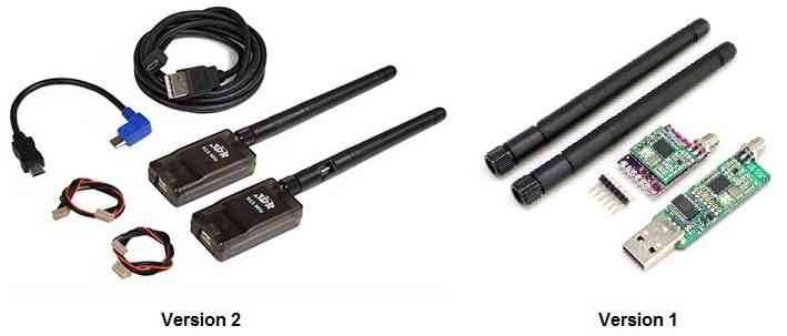
This article provides advanced configuration information for the SiK Telemetry Radio. It is intended for “power users”, and those who wish to gain a better understanding of how the radios operate.
Tip
Most users will only need the basic guide and feature overview provided in SiK Radio v2.
Monitoring the link quality
You can use the MAVLink support in the SiK Radios to monitor the link quality while flying, if your ground station supports it.
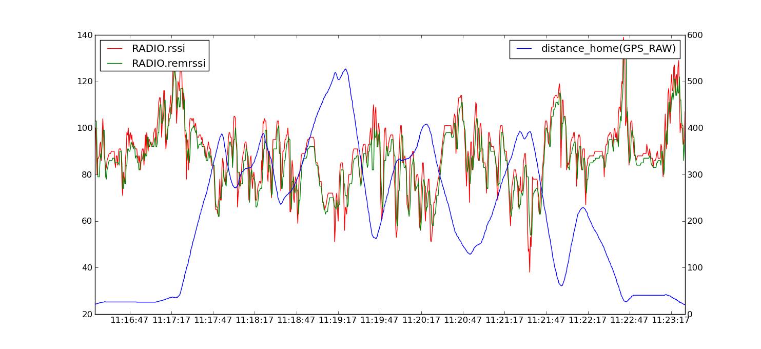
The two key message parameters are RADIO.rssi and RADIO.remrssi.
The first is the RSSI (signal strength) level that the local radio is
receiving at. The remrssi parameter is the RSSI that the remote radio is
receiving at.
Here is a typical graph of the RSSI levels for a flight at my local flying field.
The RSSI value scales approximately as 1.9x the dBm signal strength, plus an offset. See the Si1000 data sheet for the exact mapping between RSSI and dBm received signal strength, or use this approximate formula
signal_dBm = (RSSI / 1.9) - 127
Note
The reason the RSSI varies so much during this flight is that the signal is attenuated when the plane is rolled over in a turn as I was using a simple wire antenna in the plane. The RSSI values for this flight were plenty high enough for the link quality to be excellent throughout the flight using the default radio parameters.
Diagnosing range problems
If you get less range than you would expect from the above information then what you need to do is graph the noise and signal levels from a flight to work out what the problem is.
The most common source of range problems is noise. Noise is unwanted radio emissions in the same frequency range that your radio is using that interferes with the operation of your radio. The radios have telemetry logging built in to help you diagnose the source of the noise.
There are three key types of noise that are likely to affect your radios:
Noise from the electronics in your aircraft (such as your motor, ESC, autopilot etc)
Noise from your ground station computer, especially its USB bus
Noise from other people operating radios nearby that are on the same frequency as your radios
To work out what sort of noise you have, open up mission planner and choose the “telemetry logs” tab. Then choose Tlog> Kml or Graph. When the window pops up choose Graph Log and select a log from a test flight with your radios. Wait for the log to load, then choose the following items to log:
rssi
remrssi
noise
remnoise
Put all 4 values on the one graph. You will end up with a plot like this:
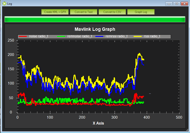
That graph shows you 4 things:
the amount of signal being received on the ground
the amount of signal being received in the aircraft
the amount of noise being received on the ground
the amount of noise being received in the aircraft
For the best possible range you want the two noise lines to be low, and the two signal lines to be high. In the above graph (taken from my SkyFun with a pair of 3DR 433 radios) you can see that the noise levels in the plane are higher than the noise levels on the ground. Also note that at the start of the flight (before I started the motor) the noise levels on the plane were lower, then they went up after I started the motor. That shows I’m getting some noise from my motor. If I wanted more range I would need to move the radio further from the motor and ESC.
Perhaps the most common source of noise with the 3DR-433 is noise from the USB bus on your ground station. That shows up as high values for the RADIO.noise value. If you get this, then you could try using a different USB cable, or a different laptop. You can also try using a USB hub between your laptop and your radio.
If the ‘rssi’ and ‘noise’ levels meet on the graph then you will lose the link. To determine what your range would be, a rough rule of thumb is to subtract the ‘rssi’ and ‘noise’ numbers, then divide by 2. That tells you your “fade margin” in decibels. For each 6dB of fade margin your range doubles. So if you have 18dB of fade margin, then you will be able to do roughly 8x whatever range you were at when you measured the margin.
Another key source of range problems is the antenna placement. Your ground station antenna should be well clear of obstructions and a couple of meters off the ground. You may need to build a stand to hold it to get the best range.
Serial and air rates ‘one byte form’
The SERIAL_SPEED and AIR_SPEED parameters are in the same form
that ArduPilot uses for the SERIAL3_SPEED parameter. If the number is
greater than 2000, it is the baud rate. Otherwise, it is the rate in
kbps, truncated to an integer. So ‘9’ means 9600 baud, ‘38’ means
38400, ‘115’ means 115200 etc.
Choosing the air data rate
The key parameter that controls the range of your radios is the
AIR_SPEED. The default is 64 (which is 64kbps) will give you a range
of over a kilometre with small omni antennas. The lower you set the
AIR_SPEED the longer your range, although lowering the AIR_SPEED
also lowers how much data you can send over the link.
The radio firmware can only support 13 possible air data rates, which are 2, 4, 8, 16, 19, 24, 32, 48, 64, 96, 128, 192 and 250. If your application needs a different air rate for some reason then we can potentially add it to the register tables. If you choose an unsupported air rate then the next highest rate from the supported list will be chosen.
What air data rate you choose will depend on the following factors:
What range you need
What data rate you will be sending
Whether you primarily send in one direction, or both
Whether you have ECC enabled
For most telemetry applications you will primarily be sending data mostly in one direction, from the aircraft to the ground station. For most people, the amount of data sent from the ground station to the aircraft is small, just an occasional control packet plus heartbeat packets.
If you are using a joystick to control your aircraft then you will be
sending a lot more data from the ground station to the aircraft, and in
that case you may find a higher AIR_SPEED is needed, although your
range will be reduced.
The ECC parameter makes a big difference to the data rate you can
support at a given AIR_SPEED. If you have ECC set to zero, then no
error correcting information is sent, and the radio uses a simple 16 bit
CRC to detect transmission errors. In that case your radio will be able
to support data transfers in one direction of around 90% of the
AIR_SPEED.
If you enable ECC, then the data rate you can support is halved. The ECC system doubles the size of the data sent by the radios. It is worth it however, as the bit error rate will drop dramatically, and you are likely to get a much more reliable link at longer ranges.
ArduPilot will automatically adapt its telemetry rates to
what the radio can handle, by using MAVLink RADIO packets injected into
the MAVLink streams by the radio’s firmware. That allows you to
‘oversubscribe’ your link, by setting up a SERIAL_SPEED larger than
what the radios can actually handle.
The other factor in choosing the air data rate is the TDM ‘sync time’. The two radios need to work out each others frequency hopping pattern. They do this by slowly changing the receive channel while rapidly changing the transmit channel. This process of getting in sync with the other radio takes just a few seconds at high air data rates, but gets slower for low air data rates.
For most amateur UAV applications the default AIR_SPEED of 64 with
no ECC enabled will be good.
Error correction
Warning
Using error correction is no longer recommended due to the range reduction and the fact that some newer radio chips are not capable of doing ECC and will fail to function if this option is selected.
As mentioned above, the radios support a 12/24 Golay error correcting code if you set the ECC parameter to 1. This means that for every 12 bits of data the radio will send 24 bits, calculating the bits using Golay code lookup tables. The process is reversed on the receiving end, and allows the radio to correct bit errors of up to 3 bits in every 12 bits send (i.e. 25% bit error rate).
The downside of the ECC option is that it halves your available data bandwidth. In some cases this is worth it, as you are able to sustain a reliable link over longer ranges. You will also get a lot less ‘noise’ in the serial stream.
MAVLink framing
If you set the MAVLINK option to 1 or 2 then the radio will do ‘MAVLink framing’. The MAVLink protocol is used by ArduPilot for transmitting telemetry date to a ground station. When MAVLink framing is used, the radio will try to align radio packets with MAVLink packet boundaries. This means that if a packet is lost you don’t end up with half a MAVLink packet being seen by the receiver. That partial packet would appear as line noise on your ground stations console.
If you set MAVLINK to 2, then in addition to doing MAVLink framing the
radio will look for RC_OVERRIDE packets (used for joysticks) and
ensure that those packets get sent as quickly as possible. This option
is useful if you are using a tablet based joystick for control.
The radio firmware will try to fit multiple MAVLink packets into one radio packet where possible for maximum efficiency. The highest radio packet size is 252 bytes.
The radio firmware supports both the MAVLink 1.0 and the MAVLink 2.0 transmission formats.
MAVLink reporting
If you have MAVLINK set to 1, then the radio firmware will also look for MAVLink HEARTBEAT messages coming from the serial connection. If it sees a HEARTBEAT message then it knows that the MAVLink protocol is in use, and it will start injecting MAVLink ‘RADIO’ status packets into the the serial stream.
The RADIO packets contain information about the RSSI (Received Signal Strength Indicator) level at both ends of the link, allowing the ground station or aircraft to take action in case the link quality falls too low.
The RADIO packets also contain information about error rates, and how full the serial transmit buffer is (as a percentage). ArduPilot can use this information to automatically adapt the telemetry stream rates to the data rate that the radios can sustain.
Power levels
You need to be very careful to configure your radios to stay within the legal power limits of the country you are operating in. The default power level of 20dBm is fine for the US and Australia, as up to 30dBm is allowed by the LIPD class licenses there in the 915-928MHz frequency band for a frequency hopping radio. So as long as your antennas have a gain of less than 10dBi you should be within the ISM rules.
The radio cannot support arbitrary power levels. It can only support the power levels given in the following table
| Power (dBm) | Power (milliWatts) |
|---|---|
| 1 | 1.3 |
| 2 | 1.6 |
| 5 | 3.2 |
| 8 | 6.3 |
| 11 | 12.5 |
| 14 | 25 |
| 17 | 50 |
| 20 | 100 |
If you choose an unsupported power level the radio will choose the next highest power level from the above table.
Please carefully check the EIRP (Equivalent isotropically radiated power) power limits for your country, making sure you take into account the antenna gain. The radio is a ‘DIY’ radio part and it is entirely your responsibility to ensure any use of it is compliant with local rules.
For example, if your local rules allow for a maximum of 30dBm (1W) EIRP, then if you use an amplifier with a 12dB transmit gain, and an antenna with 3dBi gain, then you will need to set TXPOWER to at most 14.
If you don’t know how to calculate it, we’ve made a tutorial for you here: Understanding dB, Watts and dBm.
Using the AT command set
The radios support a variant of the Hayes ‘AT’ modem command set for configuration.
If you connect with a serial console to a radio at the current serial baud rate, you can tell the radio to enter AT command mode by entering the sequence ‘+++’. To prevent data being seen as the command sequence there is a guard time required, so make sure you type nothing on the serial link for 1 second before and after you enter the sequence.
When you enter AT command mode you will receive a ‘OK’ prompt from the radio and it will stop displaying data sent from the other radio.
Once in AT command mode, you can give the radio either ‘AT’ commands to control the local radio, or (if successfully connected) you can use ‘RT’ commands to control the remote radio.
The AT commands available are:
ATI - show radio version
ATI2 - show board type
ATI3 - show board frequency
ATI4 - show board version
ATI5 - show all user settable EEPROM parameters
ATI6 - display TDM timing report
ATI7 - display RSSI signal report
ATO - exit AT command mode
ATSn? - display radio parameter number ‘n’
ATSn=X - set radio parameter number ‘n’ to ‘X’
ATZ - reboot the radio
AT&W - write current parameters to EEPROM
AT&F - reset all parameters to factory default
AT&T=RSSI - enable RSSI debug reporting
AT&T=TDM - enable TDM debug reporting
AT&T - disable debug reporting
all of these commands, except for ATO, may be used on a connected remote radio by replacing ‘AT’ with ‘RT’.
Perhaps the most useful command is ‘ATI5’ which displays all user settable EEPROM parameters. That will produce a report like this:
S0: FORMAT=22
 S1: SERIAL_SPEED=57
 S2: AIR_SPEED=64
 S3: NETID=25
 S4: TXPOWER=20
 S5: ECC=1
 S6: MAVLINK=1
 S7: OPPRESEND=1
 S8: MIN_FREQ=915000
 S9: MAX_FREQ=928000
 S10: NUM_CHANNELS=50
 S11: DUTY_CYCLE=100
 S12: LBT_RSSI=0
 S13: MANCHESTER=0
 S14: RTSCTS=0
 S15: MAX_WINDOW=131
The first column is the S register to set if you want to change that parameter. So for example, to set the transmit power to 10dBm, use ‘ATS4=10’.
Most parameters only take effect on the next reboot. So the usual pattern is to set the parameters you want, then use ‘AT&W’ to write the parameters to EEPROM, then reboot using ‘ATZ’. The exception is the transmit power, which changes immediately (although it will revert to the old setting on reboot unless you use AT&W).
The meaning of the parameter is as follows:
FORMAT- this is for EEPROM format version. Don’t change itSERIAL_SPEED- this is the serial speed in ‘one byte form’ (see below)AIR_SPEED- this is the air data rate in ‘one byte form’NETID- this is the network ID. It must be the same for both your radiosTXPOWER- this is the transmit power in dBm. The maximum is 20dBmECC- this enables/disables the golay error correcting codeMAVLINK- this controls MAVLink framing and reporting. 0=no MAVLink framing, 1=frame mavlink, 2=low latency mavlinkMIN_FREQ- minimum frequency in kHzMAX_FREQ- maximum frequency in kHzNUM_CHANNELS- number of frequency hopping channelsDUTY_CYCLE- the percentage of time to allow transmitLBT_RSSI- Listen Before Talk threshold (see docs below)MAX_WINDOW- max transmit window in msecs, 131 is the default, 33 recommended for low latency (but lower bandwidth)
For two radios to communicate the following must be the same at both ends of the link:
the radio firmware version
the AIR_SPEED
the MIN_FREQ
the MAX_FREQ
the NUM_CHANNELS
the NETID
the ECC setting
the LBT_RSSI setting
the MAX_WINDOW setting
the other settings may be different at either end of the link, although you will usually set them up the same at both ends.
Available frequency ranges
The following table may be helpful matching your local radio regulations to the two radio models available
| Radio | Minimum Frequency (MHz) | Maximum Frequency (MHz) |
|---|---|---|
| 433 | 414.0 | 454.0 |
| 900 | 895.0 | 935.0 |
DUTY_CYCLE setting
Most users will want to set the DUTY_CYCLE to 100. The
DUTY_CYCLE is the maximum percentage of time that the radio will
transmit packets.
The reason the duty cycle is included is that some regions of the world allow for higher transmit power or more frequencies if you have a duty cycle below a given threshold. So for example in Europe you can transmit on a wider range of frequencies in the 433 band if your duty cycle is below 10%.
When you set a duty cycle below 100% then your available bandwidth will be reduced, so you will find it will only work well for telemetry at higher baud rates. It is still quite practical to get good telemetry from ArduPilot with a 10% duty cycle, as telemetry traffic is quite ‘bursty’, so the average transmit time is not generally high anyway.
For example, you can easily receive all telemetry streams at 2Hz with
AIR_SPEED set to 128, ECC enabled and DUTY_CYCLE set to 10.
You can also set a radio to receive only by setting the DUTY_CYCLE
to 0. That will work best if you set NUM_CHANNELS to a low number,
as otherwise the clock synchronisation will be poor.
Low latency mode
The radio can be configured to use ‘low latency mode’ to improve performance for things like tablet based joysticks etc… The two parameters you should set to enable this mode are as follows:
Set
MAVLINKto 2. This turns on special checking for theRC_OVERRIDEpackets used in joystick control, to allow those packets to always be sent first. If you are using MAVLink (you probably are) there are no downsides for choosing this setting.Change
MAX_WINDOWfrom the default of 131 to 33. This will ensure that the GCS can send a packet to the vehicle at least once every 33 msecs. It is worth noting that this will lower the available bandwidth, so if you need absolute maximum bandwidth you are best off with the default of 131. Both radios on a channel must have the same value for this parameter, or they will not be able to talk to each other.
Listen Before Talk (LBT)
The radio can implement ‘listen before talk’ (LBT) functionality to
allow it to comply with a wider range of regional regulatory
requirements. LBT is a system where the radio is required to listen for
a period of time and see no signal from other radios before it is
allowed to transmit. By using a non-zero LBT_RSSI value your radio
will become more ‘polite’, by waiting until everyone else has stopped
transmitting before starting to transmit itself.
To enable LBT in your radio you need to set the LBT_RSSI threshold.
This is the signal strength that the radio considers to be an indication
that the channel is busy. If you set LBT_RSSI to zero then LBT is
disabled.
The minimum non-zero setting is 25 which is a few dB above the receive
sensitivity of the radio (-121 dBm). To setup LBT_RSSI you need to
know what signal level your local radio regulations require for LBT
functionality. Each increment in LBT_RSSI above 25 is roughly equal to
0.5dB above the radios receive sensitivity. So if you set LBT_RSSI to
40 then the radio will consider the channel to be free if the signal
strength is less than 7.5dB above the receiver sensitivity.
Alternatively, you can use this formula to get the received signal strength in dBm:
signal_dBm = (RSSI / 1.9) - 127
This formula is approximate, but quite close. See the Si1000 data sheet for a more precise graph.
You will need to lookup your local regulatory requirements to see what
LBT_RSSI setting you should use.
The LBT implementation in the radio uses a minimum listen time of 5ms, plus randomised listen time as per the European 9.2.2.2 rules.
Note that in many regions you need to implement LBT in conjunction with
AFA (Adaptive Frequency Agility). The radio implements AFA as long as
you have NUM_CHANNELS set to more than 1.
Upgrading radio firmware
The firmware for the radios is open source, and new features are sometimes added.
The easiest way to upgrade is to:
Connect the radio to be upgraded to your computer using the micro USB cable
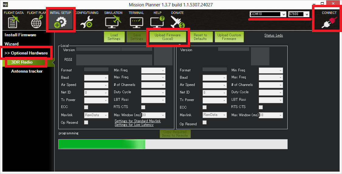
Open the Mission Planner and go to the Initial Setup | Optional Hardware | SiK Radio page.
Select the correct COM port and set the baud rate to 57600. Ensure the “Connect” button is in a disconnected state as shown in the image below..
Press the Upload Firmware (Local) button and after a short delay, the “programming” message should appear and the green bar should slowly increase from the left to right.
The above process should be performed for both radios.
Note
Occasionally a new firmware update will modify some settings so it might be a good idea to compare the settings before and after and look for changes.
Using a FTDI-to-USB cable to configure SiK radios
The recommended approach for configuring 3D Radios is to use Mission Planner, as discussed here.
If that approach doesn’t work do the following:
Connect everything and configure the ground radio:
Connect your air radio with FTDI-to-USB cable to your computer USB port & note Com port #
Use Windows | Device Manager| Ports to identify com port #
You’ll know the FTDI cable is correctly oriented on the air radio when a green LED blinks.
Connect the ground radio to a USB port on your PC & note COM port # In MP Flight Data tab, at top right, set baud to 57600 & select ground radio COM port #
In MP Flight, press Ctrl + A to open the radio configuration window. Click on Load Settings (from the ground radio)
In Mission Planner radio configuration window, (MP) check the Advanced Options box
If loaded values aren’t the same as above recommended settings, make it so, then click on Save
Configure air radio:
In MP at top right, select the air radio’s COM port
In MP radio configuration window, click on Load Settings (from air radio)
Edit the air radio’s settings (including Advanced Options) so they are exactly the same as the ground radio’s, then click on Save Settings (to air radio)
You may not be able to add a value in the Format field, that’s OK
In MP, press Configure | SiK Radio and enter exact same settings including advanced > click Save Settings.
Wait for both radios to connect (solid green LED)
Update firmware if above doesn’t work:
Click on Update Firmware while connected to each radio in turn. Then repeat the above.
To verify wireless telemetry:
Remove the FTDI to USB cable from the autopilot
Connect the air radio to the autopilot & LIPO
In MP | Flight Data tab select the ground radio COM port then click on Connect
Note
Keep in mind that while you are physically connected to a radio via a specific COM port, you can’t use the ‘Copy Required items to Remote’ button (there is no remote until you go wireless)
This section of the wiki was contributed by the Documentation User Group (DUG).
Forcing bootloader mode
If you somehow manage to get your radio in a state where you can’t upload a new firmware via the Mission Planner then you may need to force the radio into bootloader mode.
The way firmware upload normally works is the planner connects to the radio and sends a AT&UPDATE command to put the radio into bootloader mode ready to receive a new firmware. That only works if the planner can send AT commands to the radio.
If you can’t send AT commands, then you can force bootloader mode by shorting the CTS and GROUND pins on the radio while powering on. The red LED will light up when in bootloader mode.
On the air radios the CTS and GROUND pins are easy to find, as they are marked on the back of the radio (they are two of the FTDI connector pins). On the USB radios it isn’t as obvious, so this diagram may help:
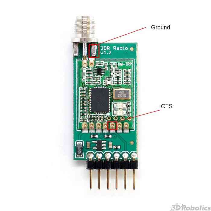
After you have the radio in bootloader mode you should be able to upload a firmware.
Technical Details
When evaluating if this radio meets your local regulations it may be helpful to know what technology it uses.
The firmware implements frequency hopping spread spectrum (FHSS) with synchronous adaptive time division multiplexing (TDM).
Specifically, the radio divides up the frequency range between
MIN_FREQ+delta and MAX_FREQ-delta into NUM_CHANNELS channels. The
‘delta’ value is a guard range to ensure that we stay well away from the
edges of the allowed band. The guard range is set to half a channel
width. The channel width is defined as:
channel_width = (MAX_FREQ - MIN_FREQ) / (NUM_CHANNELS+2)
Additionally, the radio skews the base frequency by up to one channel
using a random seed based on NETID. This means that two radios using
different NETID numbers use slightly different frequencies.
The radios use GFSK (Gaussian Frequency Shift Keying) for transmission on a particular frequency.
The TDM works by dividing up time into slices, based on multiples of 16 microsecond ticks. The time slicing is designed to give a maximum dwell time on any frequency of 0.4s (this is to meet US regulations). The TDM algorithm then works as follows:
the EEPROM parameters determine a set of TDM parameters, particularly the transmit window and silence period, both are in 16 microsecond units. You can view the results using ATI6.
the transmit window is scaled to allow for 3 full sized packets to be transmitted
the silence period is equal to twice the packet latency, for the given data rate
The two radios synchronise their clocks automatically by adding 13 bits of timestamp information to all packets. The timestamp is in 16 microsecond units.
Each radio only transmits when it is ‘their turn’. So a radio gets one transmit window worth of time, then there is a silence period when neither radio transmits, then the other radio gets its turn. We never have the situation where both radios transmit at the same time
the transmit channels are organised into a random sequence based on the
NETIDthe frequency is changed to the next channel twice for each full TDM round, during the silence periods
when not transmitting, data that comes in over the serial port is buffered in a 2048 byte buffer
to prevent the buffer from getting too much data (which increases latency and risks overflow) the radios send information on how full the buffer is to the connected device. ArduPilot adapts its telemetry rates by small amounts to keep the amount of buffered data reasonable.
The TDM algorithm is also adaptive, in the sense that when it is the turn of radio A to transmit, it can send a small token to radio B saying “I don’t need to send anything right now, you can take the rest of my timeslice”. That is how the link auto-balances for asymmetric loads
during the initial search for another radio, and any time the link is lost, the radios go into a mode where they move the receiving frequency very slowly but move the transmit frequency at the normal rate. This allows the two radios to find each other for initial clock sync. How long this takes depends on the number of channels, the air data rate and the packet loss rate.
In some regions you may need to know the distribution of radiated energy within each channel. That depends on a number of factors, but mostly the frequency deviation used for the GFSK modulation. The following formula will give you an estimate of the frequency deviation:
frequency_deviation = air_data_rate * 1.2 min freq deviation = 40 max freq deviation = 159
where frequency_deviation is in kHz and the air_data_rate is in kilo bits per second.