Archived:APM2.x Wiring QuickStart
Warning
ARCHIVED
The APM2.x is end of life for use with ArduPilot. This article is made available for existing users.
This article explains how to write up Plane’s essential components when using the APM2.x Flight Controller. The instructions for adding other hardware are covered in Optional Hardware.
Overview
Turning a RC plane into a UAV is essentially just a matter of putting an autopilot between the RC receiver and the aircraft’s servos, so the autopilot can take over control.
The way we do that is to plug female-to-female cables from the RC receiver into APM2’s inputs, and plug the servos (and motor controller for electric aircraft) into APM2’s outputs.
What you’ll need:
At least a 5-channel RC unit. 7 channels or more is highly recommended
Female-to female cables for each channel you’ll be using. These are fine.
For APM2.0 you will need a power source. For electric aircraft, this is usually the ESC. For gas/nitro powered planes, your radio will need its own battery/BEC. ArduPilot Mega normally gets its power from the RC system.
For APM2.5 you can use the supplied APM Power Module for the power
Warning
You still need an ESC or BEC to power the servos
.
Note
You can also power APM 2 from the USB cable. However, this will not power the RC output pins, so if you want to see servos move while testing APM 2 on the bench, you’ll need to connect a battery (through an ESC) to one of the output channels. It’s fine to have both an ESC and the USB cable connected at the same time.
Example Wiring Diagram
Example Wiring Diagram for a Bixler plane with APM
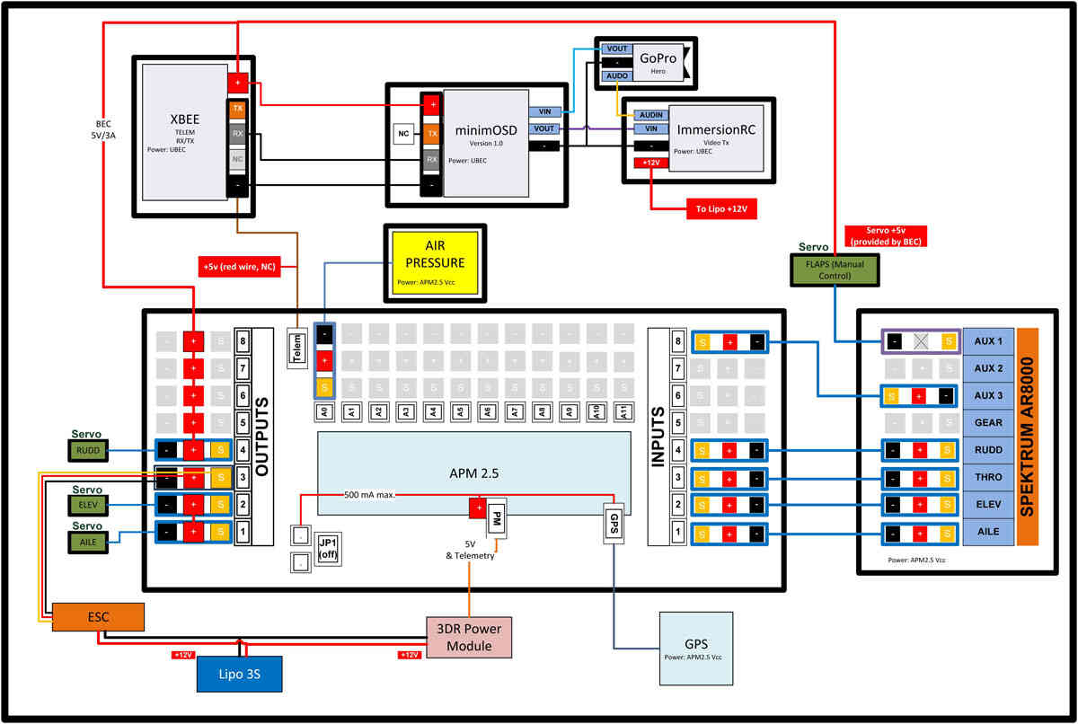
Example Wiring Diagram for aBixler plane with APM
Inputs
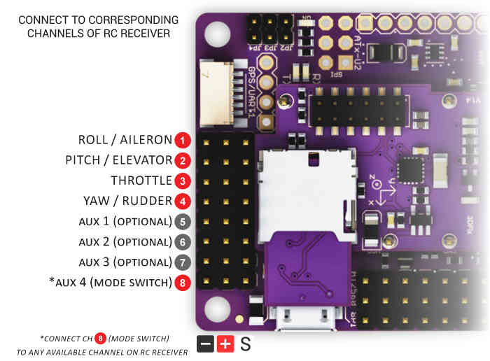
Connect your RC receiver to APM2’s Inputs with female-to-female cables in the order shown above. Each channel that you want APM to control should be connected to an Input on the APM board. Typically, the Mode Switch (APM Input 8 for !Plane) is connected to any RC receiver channel that you have assigned to a three-position toggle switch on your RC transmitter (for most people, that’s channel 5).
Note
These instructions are for Plane. Copter’s mode switch goes to APM input 5, not input 8
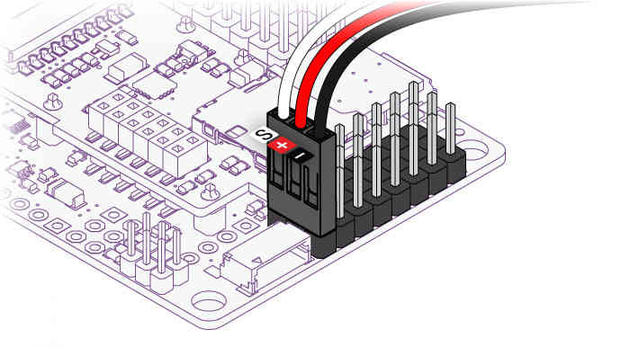
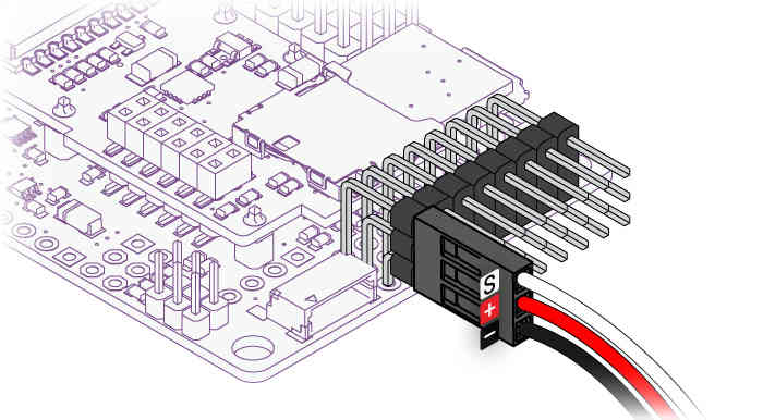
The ground (black) side of each connector should be on the outside, closest to the edge of the board, as shown here with either straight or right-angle connectors:
See also Connecting the Radio Receiver.
Note
Elevons (combined ailerons/elevator, as used in flying wings) are also supported’ just connect them to the first two channels as you would to your RC receiver. You’ll tell APM to do elevon mixing in the Mission Planner setup process.
If you’re flying a V-tail, please see the
VTAIL_OUTPUT.
option in the servo setup documentation.
Reassigning your RC transmitter stick channels:
Although the default normal transmitter stick configuration is generally the best, Plane does allow you to reconfigure them.
To reassign the RC transmitter sticks to other than the default channels:
Connect your APM’s USB port to your computer and start Mission Planner and Select the “Connect” button on the upper right..
Select the “Configuration” tab then select “Advanced Params” and the Adv Parameter List”.
Scroll down to the “RCMAP_ROLL, RCMAP_PITCH, RCMAP_THROTTLE and RCMAP_YAW” parameters.
These allow you to directly assign which radio channel (1-8) is assigned to each of the major flight functions.
This is useful when you have a flight transmitter with unusual channel assignments.
Or which does not allow easy channel reassignment at the transmitter
Additional information on these parameters may be found in the RCMAP parameters section.
Outputs
Plug your servos and other devices you want APM to control into the matching Output connectors as shown below.
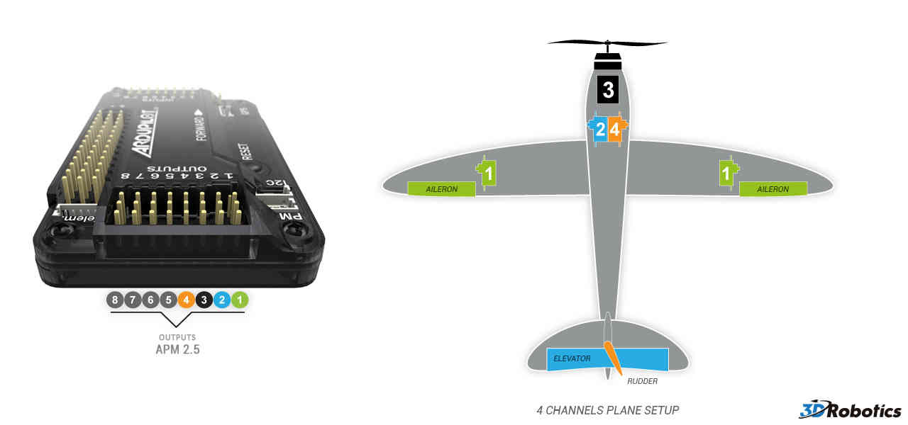
Four channel setup:
Aileron
Elevator
Throttle
Rudder
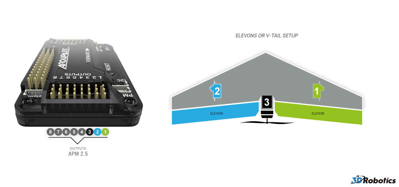
Elevon setup. At this stage it’s not critical which channel is plugged into which elevon. They can be swapped around later if needs be:
Starboard (right) elevon
Port (left) elevon
Throttle
Powering the plane
The easiest way to power the APM2.x is using a 3DR Power Module with a LiPo battery.
The Power Module will not power servos and other peripherals. For more information/alternatives see Powering the APM2.
Power Input
Single Supply
Power Options |
Nominal |
Abs MAX |
JP1 status |
Power on Output PWM connector |
5.37V +-0.5 |
6V |
JP1 connected |
Dual Supply
Power Options |
Nominal |
Abs MAX |
JP1 status |
Power on Output PWM connector |
5.00V +-0.5 |
6V |
JP1 open |
Power on Input PWM connector |
5.00V +-0.25 |
5.5V |
JP1 open |
Note
If JP1 open, separate power is required on both Input PWM and Output PWM.
Warning
Do not exceed Abs MAX input voltages when connecting power supply or you will damage your board.
Warning
Connecting USB when you have input voltages at the high end of the range (near Abs Max) can damage the board. Disconnect battery before connecting USB or test input voltages so they are within the normal specified range.
Installing it in your plane
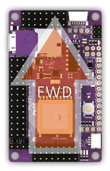
When you place APM in your aircraft, it is very important that it face the right way. The GPS connector should face forward, and the servo cables face back. The board must also be right side up, with the IMU shield at the top. Like this (note: there’s a little arrow on the bottom of the shield that point to the front, too, in case you need a reminder at the field):
When putting APM in your plane, it’s important to ensure that it’s solidly mounted and doesn’t move around in flight. It should also be as close as possible to level when the plane is in its flying orientation. Ideally, you’ll want to have it as close to the center of gravity as you can (that’s where vibration is the least) and mounted on foam tape onto a solid platform.
Connecting GPS Module
A GPS module provides enhanced positioning for autonomous flight. Connecting your GPS to your autopilot by following these steps.
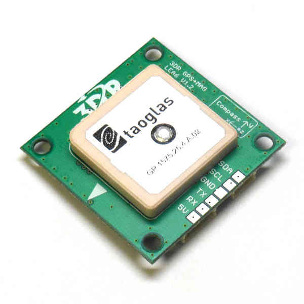
3DR GPS uBlox with Onboard Compass
3DR GPS uBlox with Onboard Compass is intended for use with APM 2.5 (for external compass). It provides enhanced compass performance because of the freedom to situate the GPS unit in an optimal position independent of the location of the APM. Place your GPS on the outside of your plane with a clear view of the sky, as far as possible from the motor and ESC, with the arrow facing forward.
Connect the GPS module to the APM 2.6 using the two cables included with the GPS as shown below.
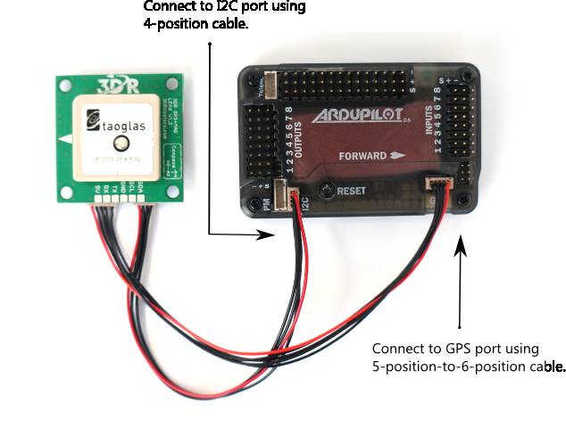
3DR GPS uBlox with Onboard Compass includes two connector cables: one 4-position cable and one 5-position-to-6-position cable. To connect the GPS module to APM 2.6, connect the GPS to the APM GPS port using the 5-position-to-6-position cable; connect the GPS to the APM I2C port using the 4-position cable.
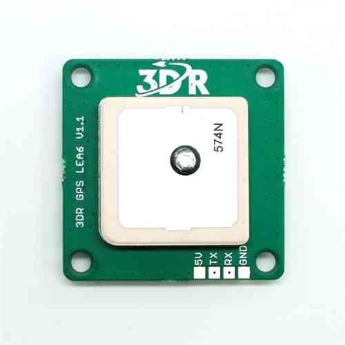
3DR GPS uBlox without Onboard Compass
3DR GPS uBlox without Onboard Compass is intended for use with APM 2.5. To install your GPS module without compass, mount to the outside of your plane with a clear view of the sky and connect to the APM 2.5 GPS port using the 5-position-to-6-position connector cable.
Tips on mounting the GPS module
It doesn’t matter which way the GPS module is oriented, as long as the square antenna side is facing up
It’s best to mount the GPS as far away from radio transmission equipment (like your telemetry or video transmitters) as possible.
Ideally, the GPS module will have a clear view of the sky. On top of your plane is a good choice.
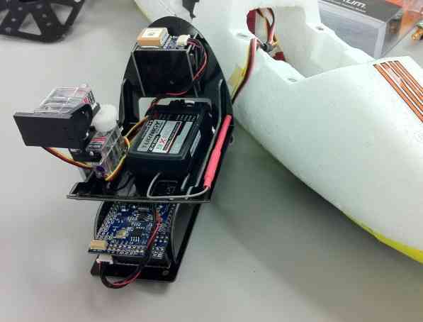
Here’s an example of one way to mount APM (and the GPS module) in an EasyStar using the 3D Robotics Electronics Chassis for the HobbyKing Bixler.
Chassis:
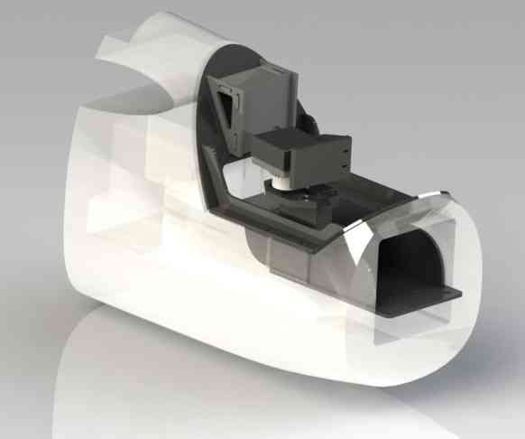
With equipment mounted: