Analog Current Monitor Calibration
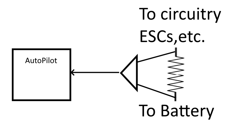
Analog current monitors usually consist of an ultralow resistance shunt used to generate a very small voltage which is then electronically amplified and delivered to the autopilot via one of its analog-to-digital (A/D) interfaces. In ArduPilot, this voltage is scaled by the BATT_AMP_PERVLT parameter to indicated the current level. The BATT_AMP_OFFSET parameter is provided to correct for any voltage offsets generated by the current monitor’s amplifier that results in output when zero current is flowing thru the shunt.
This monitor’s accuracy and repeatability across different boards is dependent on many factors: - The tolerance of the shunt resistor and amplifier components - The quality of the PCB layout which can induce parasitic errors due to high current flows - The temperature coefficient of the components since high currents can cause localized heating in some cases.
Note
many of these issues do not occur if using a HALL-EFFECT current sensor instead of a resistive shunt. Unfortunately, those are more bulky and expensive and are not practical for use on autopilots with integrated current sensors.
The net result is that shunt current sensors usually need their ArduPilot parameters tweaked to achieve good results. There are two main methods for calibration: #. Using a good ammeter. Hobby grade devices such as the GT Power Meter or inexpensive DVM types can be used to set the scale and offset. #. Empirically, by test flying and comparing the used mah reported for the flight vs how much charge is put back into the battery during recharge.
Using an Ammeter
Attach the ammeter and power the vehicle with its battery. Connect to the GCS and note the current reported.
Adjust the BATT_AMP_OFFSET parameter to match the ammeter.
Arm and throttle up the vehicle. For Copters this can be done with the propellers reversed to hold the vehicle down. For Plane, it should be secured (A helper is advised) to prevent movement. Rover will need some way to load the wheels.
Warning
be safe! make sure you or someone else cannot be injured while doing this!
The throttle level should stimulate current consumption close to the expected normal vehicle flight condition (ie like cruising level in Plane or hovering in Copter).
Note the difference between the ammeter and what the GCS reports and adjust the BATT_AMP_PERVLT to match.
Recheck the idle current and re-adjust the BATT_AMP_OFFSET, if needed. There will be some interaction between it and the BATT_AMP_PERVLT so some repetition of the above may be needed.
Its always good to use the process explained next to tweak the BATT_AMP_PERVLT parameter after a real flight or two.
Empirical Adjustment
Power the vehicle on the bench with its battery and note the reported current to the GCS. As a guess, normally it should read in the .2 to .4A range with the autopilot and peripherals powered. If a VTX is also in the system, it could be in the .6A range. Adjust BATT_AMP_OFFSET to get that reported value.
Test fly with a lengthy period in its normal flying condition (ie one takeoff, one landing only). Try to use at least 50% of the battery.
From the flight log determine how much battery was consumed, re-charge it and note how much was put back. This is usually about 105% of what was consumed. Adjust the BATT_AMP_PERVLT param according to this:
(amount of charge put back into battery/ reported used charge ) * current value becomes the new value for BATT_AMP_PERVLT
Readjust the BATT_AMP_OFFSET value on the bench
Test fly again, iterate as needed.