ARCHIVED (applied to 4.1 firmware and earlier)
Roll, Pitch and Yaw Controller Tuning
These instructions will teach you how to tune the roll, pitch and yaw response of your aircraft. This is the first tuning you should do with a new aircraft, as everything else relies on getting this right.
Tip
We strongly recommend that you use AUTOTUNE to perform roll/pitch/yaw tuning. The instructions in this article should be used if you are unable to fly.
Note
The default values for the roll and pitch controllers in Plane are quite deliberately too small for most aircraft. This is because small values will cause ArduPilot to not navigate well and be sluggish, but are less likely to cause the aircraft to crash. The pitch defaults also have a large ‘I’ gain, to try to compensate for poor initial CG location. Once trimmed via SERVO_AUTO_TRIM, this value should be set to 1/5th of the ‘P’ gain and full tuning done, as instructed below.
Preconditions
The following instruction assume that:
Your model is trimmed
You have done your radio calibration
You have calibrated your airspeed sensor
You have leveled the autopilot
You have set your autopilot and transmitter to be able to select FBW-A mode
You have checked your pitch roll and yaw angle on the HUD and verified that they match the rotation of the model
Ground Checks
On the ground select FBW-A mode
Rotate your model nose up - you should see the elevators/elevons deflect down
Rotate your model nose down - you should see the elevators/elevons deflect up
Roll the model to the right - you should see the left aileron/elevon go up and the right aileron/elevon go down.
Roll the model to the left - you should see the left aileron/elevon go down and the right aileron/elevon go up.
Level the model - the control surfaces should be close to neutral. There will be a little bit of displacement, but any more than 10% of your maximum throw indicates that the autopilot has not been leveled or the radio calibration needs to be repeated.
With the model level apply left and right roll stick inputs on your transmitter - the controls should deflect in the same direction that they would in manual mode.
With the model level apply up and down pitch stick inputs on your transmitter the controls should deflect in the same direction that they would in manual mode.
If you have an airspeed sensor enabled then blow air towards the front of the pitot tube and watch the HUD. You should see the airspeed reading increase
Flight testing
Ideally you will need a second person to do this - one person to fly the plane and one person to adjust the parameters. To follow the manual parts of this procedure you need to be a proficient RC pilot or have someone who is available to help you. Otherwise you will need to start at step 2 on the Initial Assessment and be more cautious with control gain adjustment, increasing them in small steps.
Initial Assessment
Take-off in manual and adjust the trims and throttle to a cruise position so that the plane flies straight and level at a speed that you are comfortable with. This will normally be somewhere between 30 and 60% throttle depending on how overpowered your model is.
With the plane flying away from you switch to FBW-A. It should continue to fly wings level and at a fairly constant height (it may climb or descend slowly). If it wants to roll or pitch more than a small amount then there is a problem with the model’s trim, autopilot level or radio calibration and you need to solve that first before proceeding further.
If the model starts to wag its wings, then the default
RLL2SRV_Pvalue is too high for your model (this is unlikely but could happen) and you need to switch back to manual immediately and ask your assistant to halve theRLL2SRV_Pparameter before switching back into FBW-AIf the model starts to porpoise, the default
PTCH2SRV_Pvalue is too high (this is unlikely but could happen) and you need to switch back to manual immediately and ask your assistant to halve thePTCH2SRV_Pparameter before switching back into FBW-A
Roll Control Tuning
Method 1
This method is the simplest, but won’t give the best result. For those
users familiar with tuning the old PID controllers, the
RLL2SRV_P, RLL2SRV_I and RLL2SRV_D gains have the same
effect, but there are some additional values that can be set by more
advanced users.
With the model in FBW-A mode, put in a rapid bank angle demand by pushing the aileron stick all the way over, hold it for a couple of seconds and then release. Do the same in the other direction. You want the model to roll quickly and smoothly to the new bank angle and back again without overshoot or any wing ‘rocking’. If the roll response is too slow, then progressively increase
RLL2SRV_Pin increments of 0.1 until you are happy with the response.If you get bank angle oscillation or overshoot, then you need to reduce
RLL2SRV_P. If at this point you still don’t have sufficient response then you need to follow Method 2.Once you are happy with the roll response you should now slowly increase the
RLL2SRV_Ito give the controller some “I gain” to allow it to cope better with wind. A value of 0.05 will work for most models. If you see overshoot or oscillation when raising the I value then halve it.
Method 2
This method will give a better result, but requires more caution because step 2 can produce a high frequency instability that can overheat the aileron servo(s) if allowed to continue.
With the model in FBW-A mode, put in a rapid bank angle demand, hold it and release. Do the same in the other direction. You want the model to roll quickly and smoothly to the new bank angle and back again without overshoot or any wing ‘waggle’. If the roll response is too slow, then progressively increase the
RLL2SRV_Pgain in increments of 0.1 until you are happy with the response or you start to get oscillation in bank angle or overshootIncrease
RLL2SRV_Din increments of 0.01 until it it starts to oscillate, then halve it. Do not go above 0.1 forRLL2SRV_Dwithout checking the temperature of your servos when you land as in extreme cases turning up this gain can cause rapid servo movement and overheat the servos leading to premature failure.Now start to increase the integrator gain
RLL2SRV_Iin steps of 0.05 from its default value of zero until the bank angle starts to overshoot or oscillate, then halve it.
Tuning tips
Select the tuning box on the bottom of the Mission Planners Flight Data page. You should get a scrolling black window above the map. Double click in the black window and you should get a list of parameters to plot. Change the selection until you have the roll and nav_roll plotted. Nav_roll is the demand and roll is the response. You can use this to look for overshoot and other behaviour that isn’t so obvious from the ground looking at the model.
Check for any steady offset between nav_roll and roll. If you have followed the basic method you may see an offset which can be removed by setting
RLL2SRV_Ito a small value (say 0.01) which will allow the control loop to slowly trim the aileron demand to remove the steady error.Although the autopilot will prevent the integrator from increasing if the maximum aileron is exceeded, there is additional protection provided by the
RLL2SRV_IMAXparameter. This parameter sets the maximum amount of aileron (in centi-degrees) that the integrator can control. The default value of 1500 allows the integrator to trim up to 1/3 of the total aileron travel. This parameter should not need to be changed unless you are trying to tune the controller to be able to compensate for large roll offsets due to system failures.The maximum roll rate can be constrained to make the model bank more smoothly by setting the roll rate limit RLL2SRV_RMAX parameter to a non-zero value. The default value of 60 deg/sec works well for most models. Setting this parameter to 0 turns the rate limiter off and can make the effect of tuning changes easier to see. If this value is reduced too far, then the roll controller is unable to keep up with demands from the navigation controller which leads to overshoot and weaving in the aircraft’s trajectory.
The time constant parameter RLL2SRV_TCONST can also be used to adjust how rapidly the bank angle reaches the demanded value. The effect of this parameter will be seen mostly in the response to small step changes in demanded roll. For larger roll demands, the roll rate limit RLL2SRV_RMAX tends to mask its effect. Making this parameter smaller will cause the aircraft to reach its demanded roll angle in less time, but only if the aircraft is capable. A very slow responding airframe may require a slightly larger setting for this parameter.
Plot the roll_speed in the tuning window. This shows the rate of roll in radians/second. A value of 1 radian/second is approximately equal to 60 degrees/second (57 to be more precise), so if you have RLL2SRV_RMAX set to 60, the maximum roll_speed when responding to a large bank angle demand (eg full bank one way to full bank the other) should be just above 1.0. A value of greater than 1.1 indicates that
RLL2SRV_Pis too high and should be reduced, whereas a value of less than 1 indicates thatRLL2SRV_Pshould be increased.
Pitch Control Tuning
Method 1
This method is the simplest and but won’t give the best result. For those users familiar with tuning the old PID controller gains, the K_P, K_I and K_D gains in this controller have the same effect, but there are some additional values that can be set by more advanced users.
With the model in FBW-A mode, put in a rapid pitch angle demand, hold it and release. Do the same in the other direction. You want the model to pitch quickly and smoothly to the new pitch angle and back again without overshoot or any porpoising. If the pitch response is too slow, then progressively increase
PTCH2SRV_Pin increments of 0.1 until you are happy with the response.If you get pitch angle oscillation or overshoot, then you need to reduce
PTCH2SRV_P. If at this point you still don’t have sufficient response then you need to check your radio calibration, the minimum and maximum pitch angles and potentially follow Method 2.Now roll the model to maximum bank in each direction. The nose should stay fairly level during the turns without significant gain or loss of altitude. Some loss of altitude during sustained turns at constant throttle is expected, because the extra drag of turning slows the model down which will cause a mild descent. If the model gains height during the turns then you need to reduce the PTCH2SRV_RLL by small increments of 0.05 from the default value of 1.0. If the model descends immediately when the model banks (a mild descent later in the turn when the model slows down is normal as explained earlier) then increase the PTCH2SRV_RLL by small increments of 0.01 from the default value of 1.0. If you need to change the PTCH2SRV_RLL parameter outside the range from 0.7 to 1.4 then something is likely wrong with either the earlier tuning of your pitch loop, your airspeed calibration or your autopilot’s bank angle estimate.
Method 2
This method can give a better result, but requires more caution because step 2) can produce a high frequency instability that unless reversion back to manual is done quickly, could overstress the plane.
Perform the tuning steps from Method 1
Increase
PTCH2SRV_Din increments of 0.01 until it it starts to oscillate, then halve it. Do not go above 0.1 forPTCH2SRV_Dwithout checking the temperature of your servos when you land as in extreme cases turning up this gain can cause rapid servo movement and overheat the servos leading to premature failure.Now start to increase the integrator gain
PTCH2SRV_Iin steps of 0.05 from its default value of zero until the pitch angle starts to overshoot or oscillate, then halve it.
Tuning tips
Select the tuning box on the bottom of the Mission Planners Flight Data page. You should get a scrolling black window above the map. Double click in the black window and you should get a list of parameters to plot. Change the selection until you have the pitch and nav_pitch plotted. Nav_pitch is the demand and pitch is the response. You can use this to look for overshoot and other behaviour that isn’t so obvious from the ground looking at the model.
Check for any steady offset between nav_pitch-roll and pitch. If you have followed the basic method you may see an offset which can be removed by setting
PTCH2SRV_Ito a small value (say 0.05) which will allow the control loop to slowly trim the elevator demand to remove the steady error. The value ofPTCH2SRV_Ican be increased in small increments of 0.05 until you are satisfied with the speed at which the control loop ‘re-trims’.Although the autopilot will prevent the integrator from increasing if the maximum elevator is exceeded, there is additional protection provided by the
PTCH2SRV_IMAXparameter. This parameter sets the maximum amount of elevator(in centi-degrees) that the integrator can control. The default value of 1500 allows the integrator to trim up to 1/3 of the total elevator travel. This should be enough to allow for the trim offset and variation in trim with speed for most models.WARNING : If
PTCH2SRV_IMAXis set too high, then there is a danger that in FBW-A, if the model has been leveled so that zero pitch is too nose-up to glide at a safe speed, that the integrator will continue to keep increasing the elevator to maintain the demanded pitch angle until the model stalls.PTCH2SRV_IMAXshould be set to a value that is big enough to allow from trim changes, but small enough so that it cannot stall the plane. The default for Plane is 2/3 of total throw, which could produce this problem. Be sure that STAB_PITCH_DOWN is setup to add negative pitch at low throttle in stabilized modes.The rate of pitch (and therefore the reduce the number of g’s) used to correct pitch angle errors can be limited setting the pitch rate limit PTCH2SRV_RMAX_DN and PTCH2SRV_RMAX_UP parameters to non-zero values. Setting these values to 560 divided by the airspeed (in metres/second) gives a limit equivalent to approximately +- 1g.
The time constant parameter PTCH2SRV_TCONST can also be used to adjust how rapidly the pitch angle reaches the demanded value. The effect of this parameter will be seen mostly in the response to small step changes in demanded pitch. For larger pitch demands, the pitch rate limits PTCH2SRV_RMAX_DN and PTCH2SRV_RMAX_UP tend to mask its effect. Making this parameter smaller will cause the aircraft to reach its demanded pitch angle in less time, but only if the aircraft is capable. A very slow responding airframe may require a slightly larger setting for this parameter.
Plot the pitch_speed in the tuning window. This shows the rate of pitch in radians/second. A value of 1 radian/second is approximately equal to 60 degrees/second (57 to be more precise), so if for example you had PTCH2SRV_RMAX_DN/UP set to 30, the maximum pitch_speed when responding to a large pitch angle demand (eg full pitch one way to full pitch the other way) should be just above 0.5. A value of greater than 0.6 would indicate that
PTCH2SRV_Pis too high and should be reduced, whereas a value of less than 0.5 would indicate thatRLL2SRV_Pshould be increased.
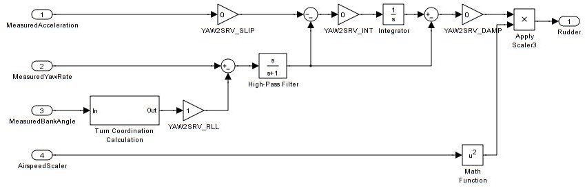
Yaw Controller Tuning
The yaw control loop can be configured either as a simple yaw damper (good for models with inadequate fin area) or as a combined yaw damper and side-slip controller. Because control of side-slip uses measured lateral acceleration, it will only work for those models that have enough fuselage side area to produce a measurable lateral acceleration when they side-slip (an extreme example of this is an aerobatic model flying a knife-edge maneuver where all of the lift is produced by the fuselage). Gliders with slender fuselages and flying wings cannot use this feature, but can still benefit from the yaw damper provided they have a yaw control (rudder, differential airbrakes, etc)
Tuning the yaw damper
Verify that the YAW2SRV_SLIP and YAW2SRV_INT gain terms are set to zero, the
YAW2SRV_RLLgain term is set to 1.0 and the YAW2SRV_DAMP gain term is set to zeroNow rapidly roll the model from maximum bank angle in one direction to maximum bank angle in the opposite direction. Do this several times going in each direction and observe the yawing motion of the model. If as the wings pass through level the nose is yawed in the opposite direction to the roll (for example when rolling from left to right bank, the nose points left) then increase the value of KFF_RDDRMIX gain until the yaw goes away. Do not use a value larger than 1.
Increase YAW2SRV_DAMP in small increments of 0.05 until the yaw angle starts to oscillate. When this happens, the tail will appear to ‘wag’. Halve the gain from the value that caused the oscillation.
Now roll the model into and out of turns in both directions. If the model has a tendency to yaw the nose to the outside of the turn, then increase the YAW2SRV_RLL gain term in increments of 0.05 from its default value of 1.0. Conversely if the model has a tendency to yaw the nose to the inside of the turn on turn entry, then reduce the YAW2SRV_RLL gain term in increments of 0.01 from its default value of 1.0. If you have to go outside the range from 0.7 to 1.4, then there is something else that needs to be sorted and you should check that you have performed step 2) correctly and check your airspeed calibration if airspeed is being used.
Tuning the sideslip controller
Tune the yaw damper first
Bring up the tuning graph window in the mission planner and plot the lateral acceleration ay.
Roll the model rapidly from full bank in each direction and observe the lateral acceleration ay. If the lateral acceleration sits around zero and doesn’t change when you roll into or out of turns then no side-slip control is necessary. You can finish at this point.
Set the YAW2SRV_INT gain term to 1.0. If this causes the yaw angle to oscillate then halve the gain from the smallest value that causes oscillation.
If you see that the y acceleration is offset or spikes up during turns, then progressively increase the YAW2SRV_SLIP gain in steps of 0.5 until the error goes away or the yaw angle starts to oscillate. If yaw oscillation occurs, then halve the gain from the value at which caused the oscillation.
Controller Overview
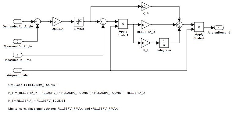
Roll Controller
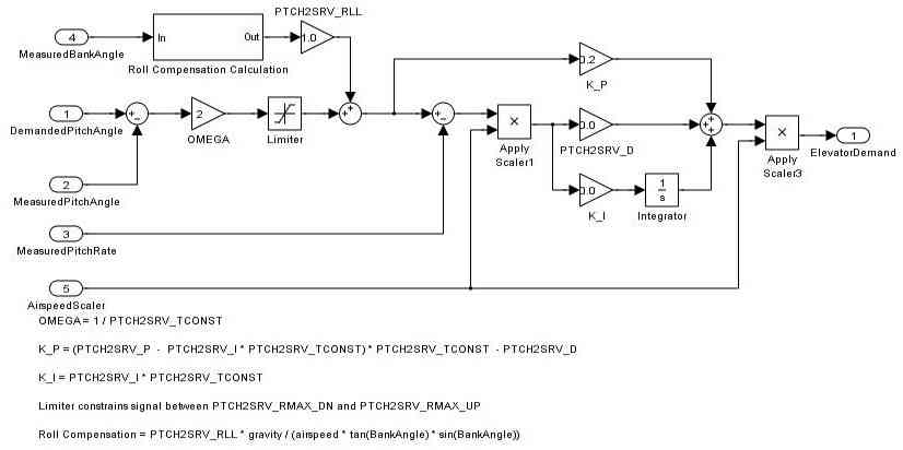
Pitch Controller
Yaw Controller