Archived:PX4FMU Overview
Warning
ARCHIVED
The PX4FMU (v1) is end of life and is not generally available for purchase. This article is made available for existing users.
This page provides an overview of the Pixhawk Flight Management Unit.
Pixhawk (FMUv2) and PX4FMU (FMUv1)
The Pixhawk (FMUv2) single board autopilot evolved from the original “PX4 system”, which consists of the PX4FMU and various piggyback boards including the PX4IO and PX4IOAR.
The Pixhawk incorporates several additional features to provide extended capabilities for our ArduPilot flight system.
A connector diagram of the Pixhawk is shown below, but Go to this link for full information on the Pixhawk
The PX4FMU/PX4IO (FMUv1) Flight Management System Includes:
The PX4-FMU (Flight Management Unit).
A powerful Cortex M4F micro-controller and flash memory for controlling flight and communications.
A socket for a plug in SD memory card.
A 3 axis gyro for determining orientation.
A 3 axis Accelerometer for determining outside influences.
A compass (magnetometer).
A barometric pressure sensor for determining altitude.
A connection for an externally mountable UBLOX LEA GPS for determining absolute position.
Stackable board interconnections for adding various peripheral boards.
Communications interfaces for USB, JTAG and Serial connections.
Connections for PPM-SUM RC radio input and servo outputs.
The PX4-IO (Input Output) Board.
Contains its own on board micro-controller and stacks with the FMU.
Direct battery input power supply.
8 High speed servo PWM outputs.
Futaba SBUS or PPM-SUM serial servo output.
A variety of PPM-SUM / SBUS input connectors.
Two user assignable relays, two 1/2 amp 5 volt outputs and an analog input port.
The PX4FLOW Smart (Optical Flow) Camera.
Specialized downward pointing camera module that uses ground texture and features to determine aircraft motion over the ground.
The PX4FLOW has the same powerful Cortex M4F micro-controller as is used in the PX4FMU.
The built in micro-controller performs on board automated binned pixel image analysis to determine motion relative to ground.
A built in 3 axis gyro enables automatic compensation for variance in aircraft tilt angle.
The PX4-IOAR Quad Carrier is a specialized interface board for the Parrot AR.Drone.
The PX4FMU circuit board comes preassembled and ready to load the firmware for your airframe using the Mission Planner.
Detailed Description
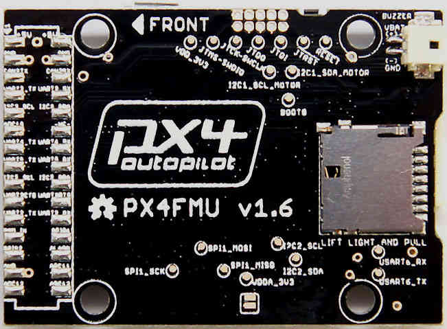
The Back of the PX4FMU board showing the SD card carrier and buzzer socket:
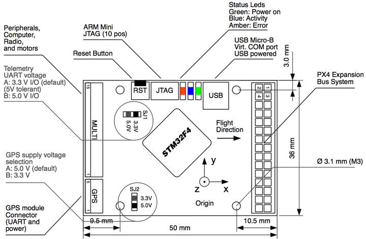
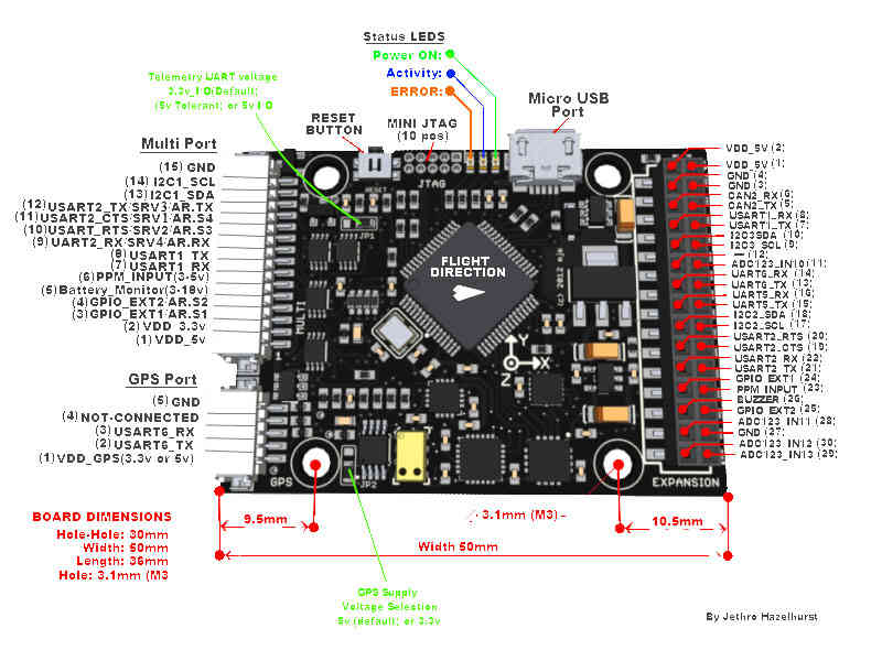
PX4FMU Connector diagram
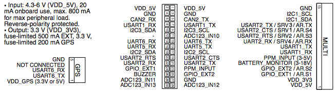
Analog and digital pins
This section lists what pins (analog and digital) are available on the PX4FMU.
PX4v1 Analog inputs
The PX4FMUv1 has the following “available” Analog input port pins which may be put to a variety of uses.
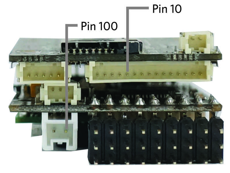
Pin 10 (High voltage analog pin):
FMU battery voltage measured on pin 5 of the 15 pin multi-connector on the end of the FMU board. It has 5.7:1 scaling, allowing it to measure up to 18.8V.
Located on pin 5 of the DF13 15 pin “multi-connector” of the PX4FMU board.
This pin can accept up to 18.6 volts. (You can add an additional resistor divider and set the scaling appropriately for higher voltages).
With the Advanced Parameter VOLT_DIVIDER set to 1 voltage can be read directly.
For old releases VOLT_DIVIDER needed to be set to 5.66 for direct voltage scaling.
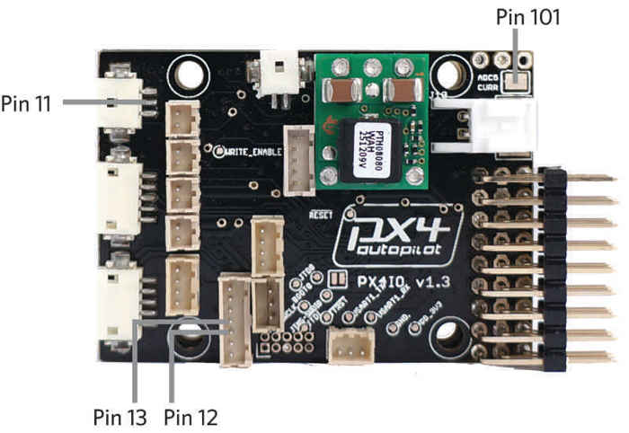
Pin 11 (Analog airspeed input pin)
Located on pin 2 of the 3 pin “FMU-PRS” DF13 connector on the PX4IO board.
Generally used in Plane for the Air Speed Sensor with VCC on pin 1, Sensor on pin 2 and Ground on pin 3.
Plane Advanced Parameter: ASPD_PIN set to 11.
This pin is directly connected to the ADC on the PX4FMU.
This pin can accept up to 6.6 volts (it has an internal voltage divider with 2:1 scaling).
Pin 12 (Analog 2 input)
Located on pin 3 of the “FMU-SPI” port on the PX4IO board.
Commonly used for Sonar
Copter and Rover Advanced Parameter: SONAR_PIN set to 12
This pin is directly connected to the ADC on the PX4FMU.
This pin can accept up to 3.3 volts.
Pin 13 (Analog 3 input)
Located on pin 4 of the “FMU-SPI” port on the PX4IO board.
Commonly used for Sonar 2 in dual Sonar installations.
Rover Advanced Parameter: SONAR2_PIN set to 13
This pin is directly connected to the ADC on the PX4FMU.
This pin can accept up to 3.3 volts.
Pin 100 (Battery voltage measured on the power connector on the IO board. Limit is 18V).
A virtual analog input pin for voltage of a battery connected to the 6V to 18V input of the PX4IO voltage regulator.
This is the normal pin to use for LiPo monitoring on the PX4IO.
If using this pin then set VOLT_DIVIDER to 1 for correct battery voltage reading.
Virtual “pin” 100’s input comes only from the battery power in jack on the PX4IO board.
This “pin” is not brought out for separate user access.
This pin is separate from the Pin 10 high voltage analog pin on the PX4FMU listed above which can also be used as a battery voltage monitor.
Pin 101: Battery current measured on the pin next to the power connector on the IO board.
A virtual analog input pin for a battery current sensor connected to the “current” pin next to the power connector on the PX4IO.
Warning
- You need to be careful
to use a current sensor that will not provide over 3.3V as too high a voltage on this pin can cause the PX4IO to reset.
For use with a current sensor, a 0.1uF capacitor between this pin and ground will help reduce “noise”.
PX4v1 Digital outputs
The PX4V1 digital output pins come in two types, one is pins that give 5V when on and 0V when off, and the other are ‘relay’ pins which provide low resistance when on and high resistance when off.
Pin 111: FMU Relay pin 1
Pin 112: FMU Relay pin 2
Pin 113: IO Relay pin 1
Pin 114: IO Relay pin 2
Pin 115: IO digital accessory pin 1
Pin 116: IO digital accessory pin 2