CHDK Camera Control Tutorial
Taking Pictures Automatically during Missions with the Canon Hacker Development Kit
Looking for an easy and inexpensive way to take high quality pictures during your missions? The Canon Hacker Development Kit (CHDK) allows you to turn a Canon point-and-shoot camera into a dynamic payload through some simple scripting. This tutorial will guide you through the process of implementing this solution for automatic camera control.
First we’ll introduce CHDK: what you’ll need to get started and tips for installing it. The first section will cover adding scripts, running scripts, and securing the camera to your fixed-wing plane. This straightforward method is great for basic automatic camera control.
Next we’ll describe how to coordinate camera controls with autonomous missions by integrating CHDK with ArduPilot. Although more complex, this implementation provides excellent functionality for taking pictures automatically at waypoints. Finally, we’ll show a fun application where you can map an area by creating a composite image of still photos.
Taking pictures automatically: What is CHDK?
Canon Hacker Development Kit (CHDK) is a free, experimental development tool that allows you to temporarily hack a Canon camera. With all the features of a DSLR unlocked to your control, a hacked camera is a smart payload that can read scripted functions such as shoot, zoom, and (importantly for later on) read the power applied to its USB port.
To use CHDK, you will need:
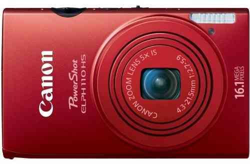
A supported Canon camera
CHDK is made possible by the ability of Canon point-and-shoot cameras to read software off an SD flash memory card. A team of developers has created Canon Hacker Development Kit to take advantage of this capability on only certain Canon cameras. For this tutorial, you will need one of the Canon point-and-shoot cameras listed on the CHDK wiki as officially supported by CHDK.
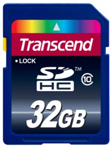
An SD card
We recommend an SD card that can be written to every two seconds and can store the amount of pictures you plan to take during your mission. You’ll also need an SD card reader for your computer.
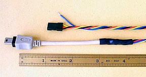
A CHDK USB cable
We use the gentWIRE USB with two channels, available here (half way down page). This cable is necessary for integrating CHDK with ArduPilot and is not required to use the intervalometer script function.
Hacking your camera
First you’ll need to install CHDK onto your camera, so naturally, you’ll need STICK: Simple Tool for Installing CHDK (available for Windows, Mac, and Linux). (You’ll also need to have Java installed on your computer.)
Follow this link to the STICK instructions page, click on “STICK zip file” under the Downloading and Installing section to download STICK. Once installed onto your computer, STICK is easy to use: take a picture with your camera, connect the SD card to your computer, and drag the picture into the STICK window. This nifty tool will download the appropriate CHDK build and prepare your SD card automatically. The STICK instructions page has some helpful tips for issues caused by certain operating systems.
Adding a script to the SD card
CHDK allows you to automate your camera’s functionality by running scripts off an SD card. CHDK scripts can be written in both UBASICand Lua: simple, easy-to-use programming languages. For this tutorial, we’ll use UBASIC scripts with file extension .bas.
Note
UBASIC script files must carry the extension .bas to function.
One of the easiest and most useful ways to apply CHDK to your mission is to take pictures automatically at intervals during flight. We’ll do this by adding an intervalometer script to the SD card. Our friends at Drone Mapper have created a great CHDK intervalometer script that can be found in Drone Mapper’s CHDK documentation or viewed by clicking here. Copy the intervalometer script into a text editor and save the file as DM_interval.bas.
This script will measure time intervals for five minutes and trigger the camera shutter every two seconds. These default parameters work well for us (results in about 150 pictures), but if you would like to modify them (for example, to take a pictures every five seconds), see CHDK Wiki’s page regarding scripting parameters for UBASIC.
To load the script onto the camera, unlock your SD card (by sliding the switch on the slide of the SD card to the unlock position), connect it to your computer, and open the SD card’s file structure. Select the CHDK folder followed by the Scripts folder. Copy the script file (DM_interval.bas) into the Scripts folder.
3. Flying with your camera
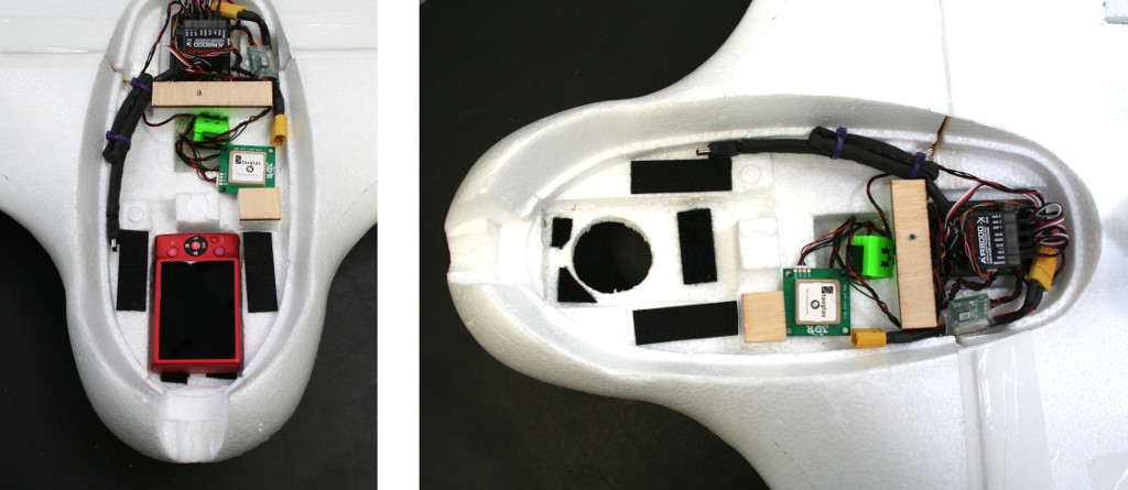
Before you’re ready for takeoff, you’ll need to pack the camera into your vehicle. For best results using plane, position the camera with the lens pointing down in the center of the plane. You may need to modify your plane’s body to create a space for the camera. Be sure to set the plane’s center of gravity with the camera in place, and keep in mind the safety of the camera in case of failure. Check out our setup for inspiration; we used velcro strips to secure the camera in place.
Activating scripts before flight
Prior to launching your plane, it is necessary to activate the intervalometer script on the camera. Make sure the SD card is locked and loaded into the camera and the camera is turned on. When you’re ready to launch your plane, enter ALT mode by pressing the Print or Play button on the camera (for more information consult the CHDK wiki). Press the Menu button to access the main CHDK menu. Select Load Script from File; select DM_interval.bas. Press the shutter button to run the script. (You can also use the shutter button to stop the script.) Once you start the script, the camera will automatically begin taking pictures after a delay of five seconds, so be sure to take that into account when launching your plane.
Integrating CHDK with ArduPilot
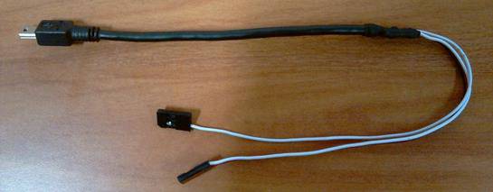
To integrate your CHDK setup with ArduPilot, you will need a CHDK cable (pictured across) that connects the autopilot’s output signal pins with the camera’s USB port. We used Gentles’ gentWIRE-USB2 cable. (Stay tuned for a 3DR CHDK cable.)
CHDK cables work by translating pulse width modulation (PWM) output by the autopilot into USB power pulses that can be read by the camera. It does this by establishing a range of how long power is applied to the USB port (ex: 40-80 ms) and assigning that range to a PWM value corresponding to a channel switch position (ex: channel 1 middle). The table below shows the corresponding values between the switch position on the RC transmitter, the autopilot’s PWM output, and the camera’s USB power.
Switch position |
PWM (µs) |
USB power (ms) |
Channel 1 up |
1,900 |
<50 |
Channel 1 mid |
1,500 |
>40 and <80 |
Channel 1 down |
1,100 |
>70 and <110 |
Channel 2 up |
1,900 |
>100 and <140 |
Channel 2 mid |
1,500 |
>130 and <170 |
Channel 2 down |
1,100 |
>160 and <120 |
Each switch position can be assigned to a script function. This means that you can script up to six different camera controls such as triggering the shutter and setting different levels of zoom. For this tutorial, we’ll show you how to set up three functions using only the first channel, but this process can be followed to utilize the full six options if you choose to.
Configuring the CHDK cable for use with ArduPilot
First we need to select an RC channel to assign to CHDK’s channel 1. Connect your plane’s autopilot to Mission Planner. Go to Configuration | Radio Calibration to locate an available channel and its corresponding three-position switch on your RC transmitter. For this tutorial, we’ll use channel 7. (If you decide to use a different channel, substitute your channel wherever we input channel 7.) Don’t disconnect your autopilot yet.
Before we fly, we’ll need to test the integration between this channel and the CHDK cable by manually changing the switch position and observing the result. In order to allow manual control of this channel, we need to change an important parameter in Mission Planner. Under Configuration | Standard Parameters, scroll about 4/5 of the way down to find the Servo out function parameters for each channel. Find the parameter that corresponds to your camera control channel. For us, it’s Servo out function (SERVO7_FUNCTION or RC7_FUNCTION).
Note
Set this parameter to Manual whenever you want to control your camera using your RC transmitter; set to Disabled when you want the autopilot to control the camera automatically.
Since we’re using the RC transmitter to test the CHDK cable, set Servo out function to Manual. Select Write Params before disconnecting your autopilot.
Once you’ve chosen your camera control channel, you’ll need to connect your CHDK cable to the autopilot’s output pins. Connect either of the pin connectors on the CHDK cable to the autopilot output pins corresponding to your camera control channel (black cable on the outside). For example, we connected our CHDK cable to the channel 7 output pins on the autopilot. Make sure no input pins are connected to the autopilot for that channel.
For Pixhawk, connect the CHDK cable to aux out pin 5. However, this pin outputs only 3.3V, and 5V are required to trigger CHDK. To convert to 5V, you’ll need to integrate a step-up converter (like the one here from Sparkfun) in-line with the cable to trigger CHDK.
Adding a script
Now that you’ve configured your CHDK cable, we’ll add a script to control the camera when commanded by the autopilot. Let’s break down a CHDK cable UBASIC script into its main parts.
@param o Zoom-extended
@default o 100
@param i Zoom-stowed
@default i 30
@param s Zoom-shoot
@default s 10
This section defines the parameters that will be used later by the functions. @param names the parameter with a variable and a phrase; @default specifies its value. These three parameters specify zoom levels, so if you wanted to change a zoom level, you could easily do so by entering a new value after the variable following @default.
while 1
do
k = get_usb_power
until k>0
if k < 5 then gosub "ch1up"
if k > 4 and k < 8 then gosub "ch1mid"
if k > 7 and k < 11 then gosub "ch1down"
if k > 10 and k < 14 then gosub "ch2up"
if k > 13 and k < 17 then gosub "ch2mid"
if k > 16 and k < 20 then gosub "ch2down"
if k > 19 then print "error"
wend
end
This is the main body of the script. It tells CHDK to read the power pulse from the USB port (get_usb_power) and, according to what range it falls under, execute a specific function. The values here are listed in centiseconds, which is why they differ from the table shown above (5 centiseconds = 50 milliseconds).
:ch1up
print "Ch1Up-Shoot"; k
set_zoom s
shoot
sleep 1000
return

:ch1mid
print "Ch1Mid-Stowed"; k
set_zoom i
sleep 1000
return

:ch1down
print "Ch1Down-Extended"; k
set_zoom o
sleep 1000
return

:ch2up
return

:ch2mid
return

:ch2down
return
This is where the script defines what each function will do. Since we aren’t utilizing the channel 2 options, ch2up, ch2mid, and ch2down functions are empty. The ch1up function will set the zoom to the value specified by the variable s using the set_zoom command and take a picture using the shoot command. The ch1mid function uses set_zoom to set the lens to its stowed position, and the ch1down function fully extends the lens. The print command will output the specified text to the camera’s display along with the actual output value of the USB power pulse (k).
In short, the above script will cause the following behaviors:
When channel 7 is set to the up position, CHDK will set zoom to 10 and take a picture.
When channel 7 is set to the mid position, CHDK will set zoom to 30 (stowed position).
When channel 7 is set to the down position, CHDK will set zoom to 100 (extended position).
Click here to view the above script, copy into a text editor, and save as 3DR_Shoot.bas. Now that you’re familiar with how the script works, you can easily change the commands of each function. For example, you can add a shoot command to ch1down or change one of the zoom level parameters. If you’re utilizing the channel two functions, you can easily add commands to those functions in the same format shown above.
Add the script file to the SD card as described in the previous section.
Testing the CHDK cable
Testing the CHDK cable will ensure that our camera controls execute as expected and is a great opportunity to test for potential noise created by your equipment setup.
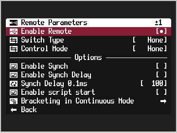
To tell CHDK to listen to the cable, we need to set the Enable Remote parameter. On the camera, access the CHDK menu, select Remote Parameters, and select Enable Remote as shown. This setting must be enabled to allow communication with the CHDK cable.
Connect the CHDK cable to the camera’s USB port, and run 3DR_Shoot.bas. Test the result of each switch position. The resulting behaviors should reflect those listed in the previous step. Observe the USB pulse values output to the camera display, and compare them with the ranges show in the code. If you encounter problems, see the Advanced Topicssection below for additional testing and troubleshooting information.
Programming camera controls in Mission Planner
Mission Planner allows you to program servo outputs as events at waypoints. By using this feature, we can add a command to output a PWM value (corresponding to a switch position and function) after the plane achieves each waypoint.
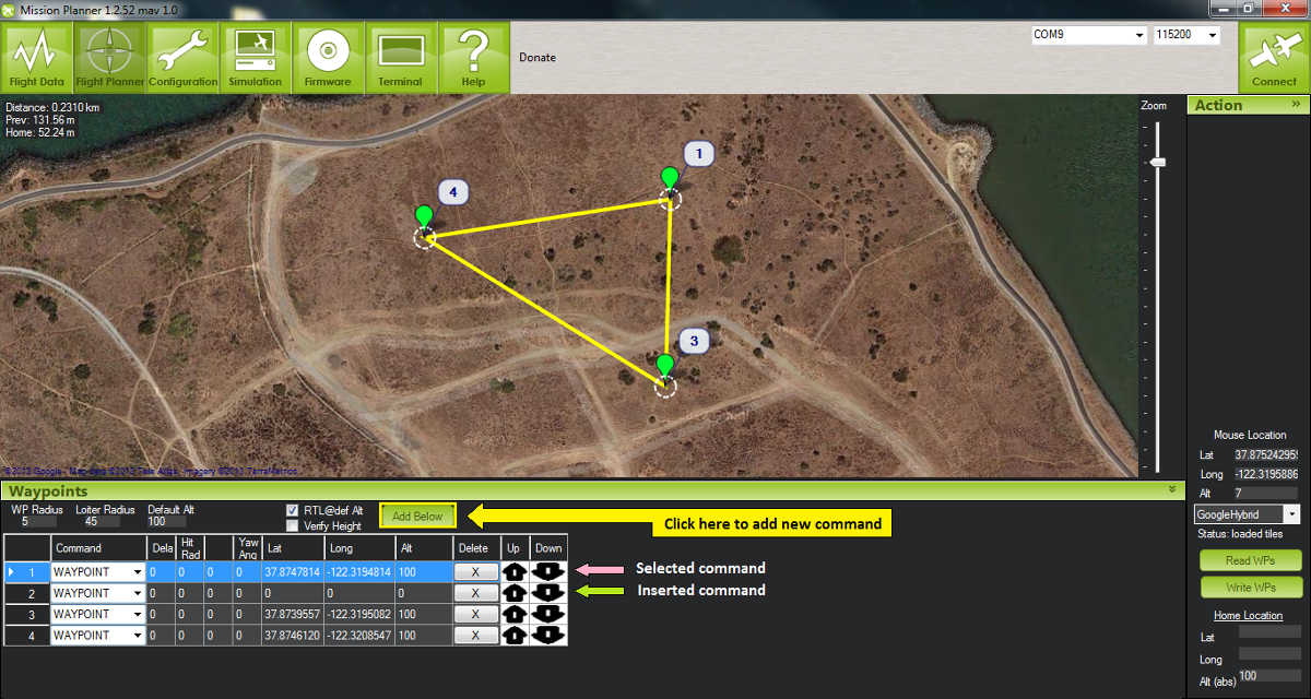
Once you have your waypoints configured in Mission Planner as shown below, select your first waypoint and click “Add Below”.
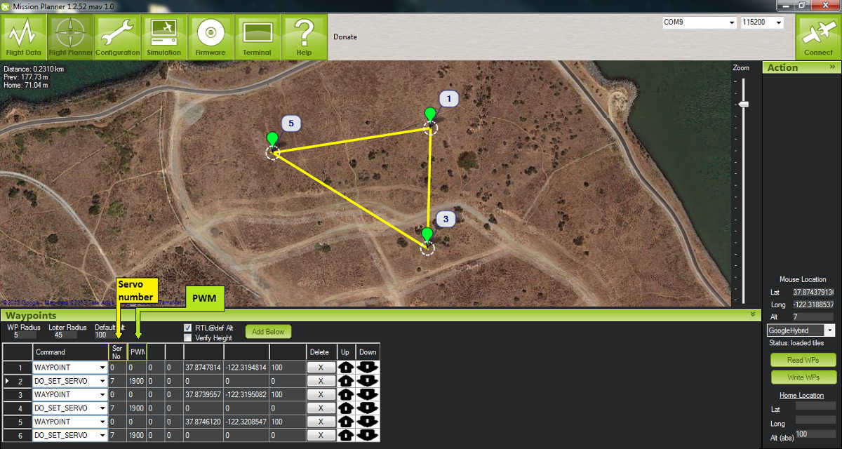
For your new command, set Command type to DO_SET_SERVO. (This tells the autopilot that this command means output to a servo.) Set Ser No(servo number) to the number of your camera control channel (ex:7). (This tells the autopilot where to output: for us, servo channel 7 is the CHDK cable.) And set PWM to 1900. (This value tells the autopilot what to output: 1,900 microseconds of pulse width modulation corresponds to the high position under which the shoot command is located). Repeat this process for each waypoint at which you would like to take a picture. The screen below shows a shutter command correctly applied at each of three waypoints.
Note
Columns in the Waypoints table accrue different meanings based on the type of command currently selected. These column definitions only become visible when the command is selected as different parameters apply to different types of commands.*
Since we’re using the autopilot to control the camera, we need to set the Servo out function (RC7_FUNCTION or SERVO7_FUNCTION) parameter to Disabled (under Standard Parameters). Write waypoints and parameters to the autopilot.
Ensure that your camera and autopilot are connected correctly. Run 3DR_Shoot.bas prior to launch. Fly your mission according to standard practices and safety procedures.
Creating a composite image
One of our favorite applications of CHDK is creating a map of an area by stitching automatically-captured pictures into a composite image. We’ll use the same 3DR_Shoot.basscript that we used in the previous section. The process is similar to setting shutter triggers at waypoints, only to make sure we capture the entire area we need more frequent, more regular waypoints. We’ll do this automatically using Mission Planner’s Grid V2 automatic waypoint function.
Setting waypoints with GridV2
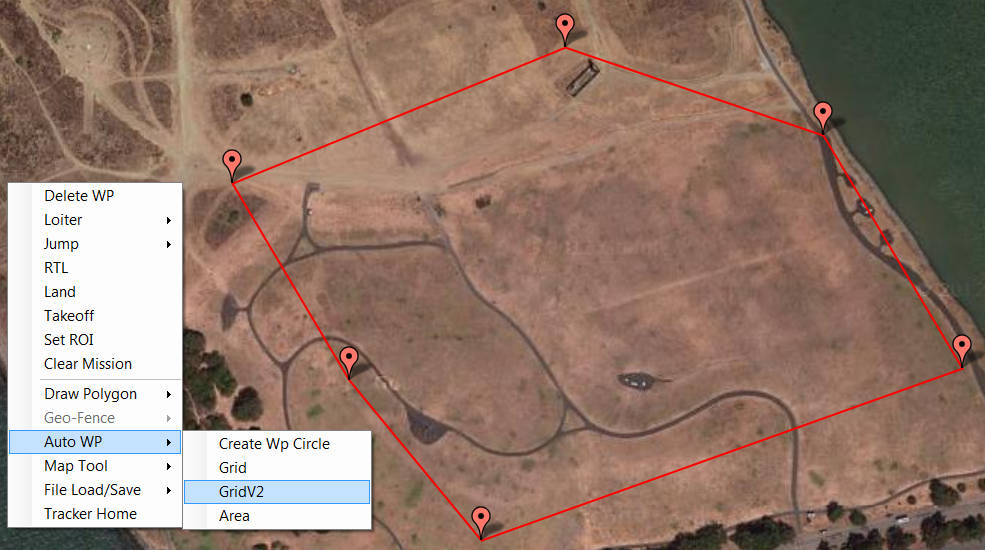
First locate the area you wish to map in Mission Planner. Right-click and select Draw Polygon| Add Polygon Point. Add polygon points until you have created a polygon around the area you wish to map. Once you are satisfied with your polygon, right-click and select Auto WP | GridV2 as shown below.
Input a relative altitude (100 feet is fine if you are unsure). Input a distance between lines; the larger the number, the fewer waypoints you’ll end up with. When prompted, enter a distance between each waypoint; the same rationale applies here. Enter line direction; the waypoints below show a line direction of 70. When prompted to add camera triggers, input “Yes”; this will create a command after each waypoint, it will not automatically set up your CHDK commands. We recommend experimenting with these settings until you find the waypoint configuration that is right for your mission. You should now have a grid of waypoints mapped onto your polygon as shown below.
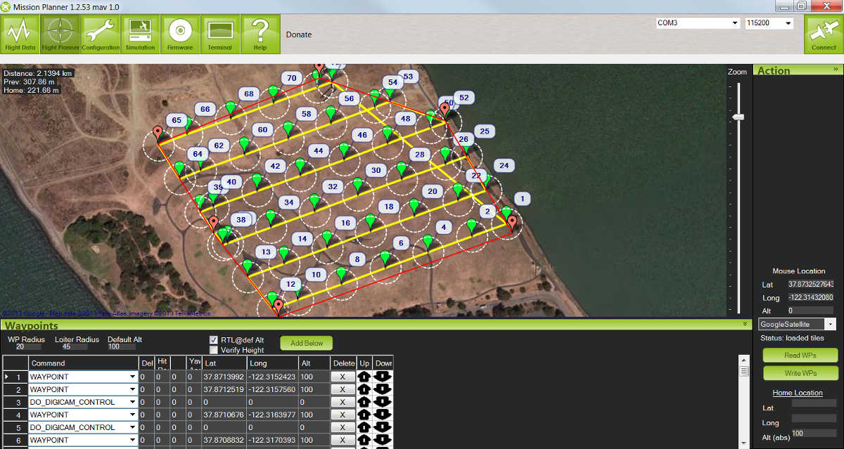
Here is where we have to switch our automatic functionality for some manual labor. GridV2 has created a command after each waypoint with command type DO_DIGICAM_CONTROL. However, for our CHDK setup, we need command type DO_SET_SERVO. For each DO_DIGICAM_CONTROL command, change command type to DO_SET_SERVO, set Ser No to 7 (or whichever channel you’re using), and set PWM to 1,100 (to call the 3DR_Shoot.bas function that takes a picture).
When run, this mission returns a set of images that can be stitched together to create a map of the selected polygon.
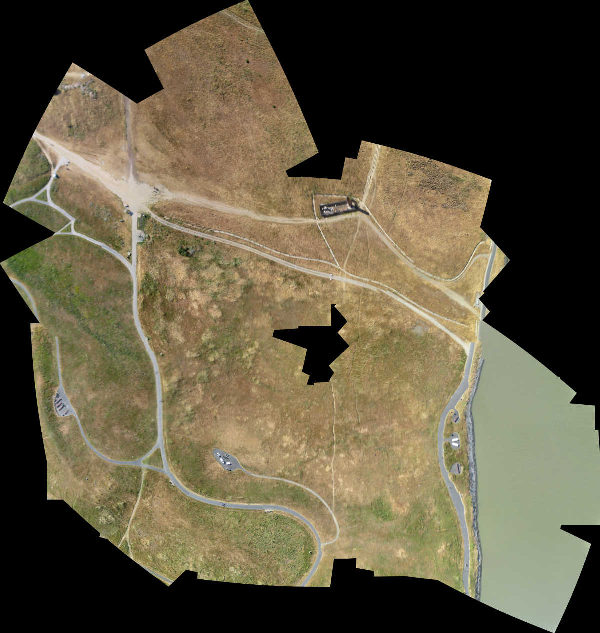
Stitching images
Microsoft Image Composite Editor (ICE) is a great, free tool for automatically stitching images together into a composite. Just upload your images, and ICE will stitch them together. Here’s an example of one of our composites:
We hope this solution provides some enhanced functionality to your missions and expands your autonomous imaging capabilities. For more information, check out the Advanced Topics section below.
Appendix
Camera Settings
The following settings will help ensure that you get the best results from your aerial imagery. The picture settings should can be adjusted based on your environment, but the listed values are a good place to start. Both the Canon settings and CHDK settings will vary from camera to camera.
CHDK settings have a tendency to be unintuitive and to reset themselves at random, so be sure to understand what each setting does and check to make sure they have not changed before you fly!
Canon Settings
Flash: Off
Function
ISO: Auto
AWB: Daylight
Image Size: L
Image Quality: Fine/Superfine
Menu
AF Frame: Center
Digital Zoom: Off
AF-Point Zoom: Off
Servo AF: Off
AF assist beam: Off
Flash Settings
Red Eye correction: Off
Red-Eye Lamp: Off
Date Stamp: Date & Time
Power Saving…
Auto Power Down: Off
Display Off: 1 min
IS Settings…
IS Mode: Shoot Only
Powered IS: Off
GPS: On
CHDK Settings
Function
Autostart: On
Save Params: ON
Remote Parameters: Enable Remote
Menu
Extra Photo Operations…
Disable Overrides: Disable
Override Shutter Speed: 1/1600
Value Factor: 1
Override Subj. Dist V: 65535
Value Factor: 1
Custom Auto ISO…
Enable custom auto ISO
Minimal: 1/1000
Clear override values @start: Disable
Advanced Topics
CHDK Cable Troubleshooting and Testing
CHDK cables work by translating pulse width modulation (PWM) output by the autopilot into USB power pulses that can be read by the camera. It does this by establishing a range of how long power is applied to the USB port (ex: 40-80 ms) and assigning that range to a PWM value corresponding to a channel switch position (ex: Channel middle).The table below shows the corresponding output values between the switch position on the RC transmitter, the autopilot’s PWM output, and the camera’s USB power. In practice, our Spektrum DX 8 outputs the values shown in the rightmost column.
Switch position |
PWM (µs) |
USB power (ms) |
Spektrum DX8 USB power readings (ms) |
Channel 1 up |
1,100 |
<50 |
30 |
Channel 1 mid |
1,500 |
>40 and <80 |
50 or 60 |
Channel 1 down |
1,900 |
>70 and <110 |
90 |
Channel 2 up |
1,100 |
>100 and <140 |
130 |
Channel 2 mid |
1,500 |
>130 and <170 |
150 or 160 |
Channel 2 down |
1,900 |
>160 and <120 |
190 |
To verify that your transmitter behaves similarly, you may want to perform a test to ensure that a valid USB power value is returned for each switch position. View the 3DR CHDK Tester script here. Copy the contents into a text editor and save as 3DRCHDKTester.bas. Load into your (unlocked) SD card by copying the file into the Scripts folder (in the CHDK folder).
Configuring CHDK cable for Testing
Before we can test the CHDK cable, we’ll need to choose a channel for camera control and configure the corresponding inputs. Connect your plane’s autopilot to Mission Planner. Go to Configuration | Radio Calibration to locate an available channel and its corresponding switch on your RC transmitter. (We’ll use channel 7.) Check the PWM outputs for the up, mid, and down positions of the channel. Compare them with the table shown above.
Before we disconnect the autopilot, we need to change an important parameter that you’ll be using often. Under Configuration -> Standard Parameters, scroll about 4/5 of the way down to find the Servo out function parameters for each channel. Find the parameter that corresponds to your camera control channel. For us, it’s Servo out function (SERVO7_FUNCTION or RC7_FUNCTION).
*Set this parameter to Manual whenever you want to control your camera using your RC transmitter; set to Disabled when you want the autopilot to control the camera automatically.*
Since we’re using the RC transmitter to test the CHDK cable, set Servo out function to Manual. Select Write Params before disconnecting your autopilot.
Once you’ve chosen your camera control channel, you’ll need to connect your CHDK cable to the autopilot’s output pins. Connect either of the pin connectors on the CHDK cable to the autopilot output pins corresponding to your camera control channel (black cable on the outside). For example, we connected our CHDK cable to the channel 7 output pins on the autopilot. Make sure no input pins are connected for that channel.
Testing the CHDK cable
Testing the CHDK cable will ensure that our camera controls execute as expected and is a great opportunity to test for potential noise created by your equipment setup.
Connect the CHDK cable to the camera’s USB port. Turn the camera on, load the 3DRCHDKTester.bas script (by selecting Load Script from File from the main CHDK menu), and press the shutter button to run the test script.
To perform the test, set each camera control channel position on your RC transmitter and observe the outputs on the display. Verify that these outputs are within the acceptable USB power ranges in the table above. If you encounter problems, you may need to shield your cable to prevent noise.
Shielding the cable
Coming soon.
GeoTagging Images
For information regarding geotagging images, more information can be found on Sandro Beningo’s step-by-step guide.
Troubleshooting
Problem: The tester script runs but does not display any output on the camera screen.
Cause 1: Do you have the parameter SERVOx_FUNCTION=1 ir RCx_FUNCTION=1 for manual override of the RC channel you are using? You can see both the PWM input and output on the Configuration | Failsafes screen in the Mission Planner.
Cause 2: Is your output rail powered? Even if you are getting the correct PWM signal out on your camera control channel, the output needs 5V DC. You can power the output rail with a jumper on JP1 as shown, which bridges the input power to the output, or by directly running power to the output.
Cause 3: Do you have the remote enabled in CHDK? In the CHDK menus: Remote parameters > enable remote. Leave the other remote settings as is.