Mission Planner Flight Data Screen
This section covers the information you will need to use the features in the Mission Planner Flight DATA screen - selected in the Top menu of Mission Planner. An Introduction provides a brief overview with pointers to the various areas of information.
Heads Up Area (HUD)
This is the area in the upper left corner of the Mission Planner Data screen. Details of what each item is can be found here
Note
You can detach the HUD to a separate window by double clicking anywhere in the window. Close the window to put it back in the main Mission Planner window.
Options
Several Options are available by right-clicking the HUD.
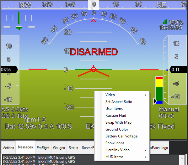
- Video:
You can start or stop recording the HUD as an .avi video stored in the logs folder.
Set MJPEG Source: Connect and display MJPEG video source from the network.
Start Camera: If a video source has been selected in the CONFIG/Planner page, start displaying it in the HUD window.
Set GStreamer Source: Connect and display Gstreamer video stream.
HereLink Video: Display HereLink video, use the same IP as when connecting MP via UDPCL to Herelink for telemetry. See Herelink documentation.
GStreamer Stop: Stop GStreamer video.
Note
In the CONFIG/Planner screen, you can select to display video from a capture source on the PC in the HUD window, and have the HUD display overlaid or not on that video.
Set Aspect Ratio: clicking this alternates between 4:1 and 16:9 aspect ratio.
User Items: You can add any of the telemetry parameters to the display by right-clicking on the HUD, clicking User Items, and checking the items you want to display. Note that you can also view all of the telemetry in the Control and Status area by clicking the Status button. If Scripting is sending NAMED_VALUE_FLOAT values, these will also appear as an item that you can display in the HUD.
Russian HUD: Toggle to/from a Russian style HUD (i.e. ground horizon fixed).
Swap with Map: swap map to this window and vice versa.
Ground Color: Click to change the ground color.
HUD Items: Toggle which items are displaying on the HUD such as heading, speed, altitude, etc.
Show icons/text: Toggle between using icons or text for the lower HUD items such as battery capacity, EKF status, VIBE status, and GPS status.
Control and Status (Lower Left)
The Control and Status area of the Flight Data screen is in the lower left-hand portion of Mission Planner. In this area, you can select any of several different tabs. Some tabs provide information (e.g. Status) and other items allow control of the vehicle (e.g. Actions) using the telemetry uplink. (Telemetry radio connection is required)
Quick: This allows a quick look at just a few telemetry values in large text. Double-click to add items. Right-click to change the number of rows/columns and move the tab to a separate window.
- Actions: Use this area to control your Auto Pilot either for testing (using USB and no motor battery) or for controlling your vehicle. You can switch modes, arm/disarm (while on the ground), enable an attached joystick, restart a mission in the air, control a camera mount, etc.
The dropdown menus on the left are for (in order from top to bottom) choosing a MAVLink action, choosing a waypoint to set, choosing a mode to set, and choosing the state of the camera mount. The buttons directly to the right of each dropdown send the selected action to the connected vehicle.
There are shortcut buttons for Auto, Loiter, and RTL modes
Joystick: Allows the user to set up a joystick attached to the ground station. See Joystick/Gamepad for more information.
Set Home Alt: Set current altitude to zero
Restart Mission: Set the current waypoint to the start of the current mission
Raw Sensor View: Shows roll, pitch, and yaw angles. Also shows gyro, accelerometer, 8 RC input channels, and 8 servo output channels.
Arm/Disarm: Arm and disarm the vehicle.
Resume Mission: Change to Auto mode at the previous waypoint.
Change Speed: This value is always in m/s and performs a DO_CHANGE_SPEED command
Change Alt: This value is in the user-selected altitude units. The default units are meters.
Set Loiter Rad: This changes the loiter radius when in Loiter mode in meters.
Clear Track: Clears the purple track line shown on the map.
Abort Landing: Commands the vehicle-specific abort landing procedure.
Messages: Messages from the vehicle that can range in importance from informational to critical. Important messages also appear on the HUD.
Gauges: This shows four popular telemetry gauges. Double click the speed gauge to change the top speed.
Status: Clicking the Status menu button will display all of the telemetry parameters
Servos/Relay: This allows the setting of any relay pins or setting/overriding RC values for channels 5 thru 14. (Use servo settings with caution, you could change flight modes)
Telemetry Logs: Use this section to view, analyze, convert, and playback telemetry logs that are recorded by Mission Planner. See Playing Back Missions with Tlogs for specifics on playing back your mission and viewing the mission in the map area.
Data Flash Logs: This provides a means to download data flash logs, analyze them, or create KML/gpx files from them. Click Review a Log to open a log file and establish a new window to view/analyze the log. Details here.
Scripts:: Automation using Python scripts and vehicle state
Note
the ability to change modes from the ground station can be restricted, by mode, using the FLTMODE_GCSBLOCK parameter.
Map Area
The map area on the right side of the Flight Data screen displays the vehicle track as it moves, provides other information, and allows the user to enter some control actions - which send commands to the vehicle (telemetry required)
Right-click on the map area to select one of these options.
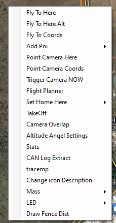
Fly to here: (Command) This is guided mode (see bottom of this page Guided Mode)
Fly to here Alt: (Command) Lets you enter an altitude.
Fly to Coords: (Command) Lets you fly to a latitude and longitude
Add POI: Lets you set, delete, save, and load Points of Interest to display on the map
Point Camera Here: (Command) Points vehicle and camera at the location of the cursor
Point Camera Coords: (Command) Point vehicle and camera at a location using latitude and longitude coordinates
Trigger Camera Now (Command): Triggers camera if setup.
Flight Planner: You can open the flight planner window in the map window area and leave the rest of the Flight Data Screen as is. Click the “CLOSE” button at top to return.
Set Home Here: (Command) Set new HOME position for RTL
TakeOff: (Command) Takeoff and loiter at input altitude. Copter and QuadPlane only.
Camera Overlap: If checked will show camera overlaps on the map during a survey mission
Altitude Angel Settings: Allows reporting and connection to Altitude Angel services
Stats : (in development)
Information/options at the bottom of the map
hdop, sats: shows information about the GPS reception quality and the number of satellites in view.
Legend: Each color corresponds to the color of the corresponding line showing directions and headings. Black is the GPS track as your vehicle travels.
Tuning: Opens/closes the tuning window. Any value in the Status list (double click) can be graphed in real-time.
Auto Pan: Checking this box will make the map follow the vehicle and thus keep the vehicle in the center of the screen.
Zoom: Shows or selects the current zoom level of the map. You can also use the:
Scroll bar: Use the scroll bar to change the zoom level of the map.