Pixhawk Wiring Quick Start
This article provides high level information about how to power Pixhawk and connect its most important peripherals.
Warning
Do not connect any servos or other devices to the PWM outputs of your receiver. The RCIN port on the Pixhawk is designed for low power devices only, and a servo or relay may draw a lot of current from the receiver. If you connect a servo directly onto your receiver while the receiver is powered from the RCIN port of your Pixhawk you may damage your Pixhawk.
Pixhawk Wiring Chart
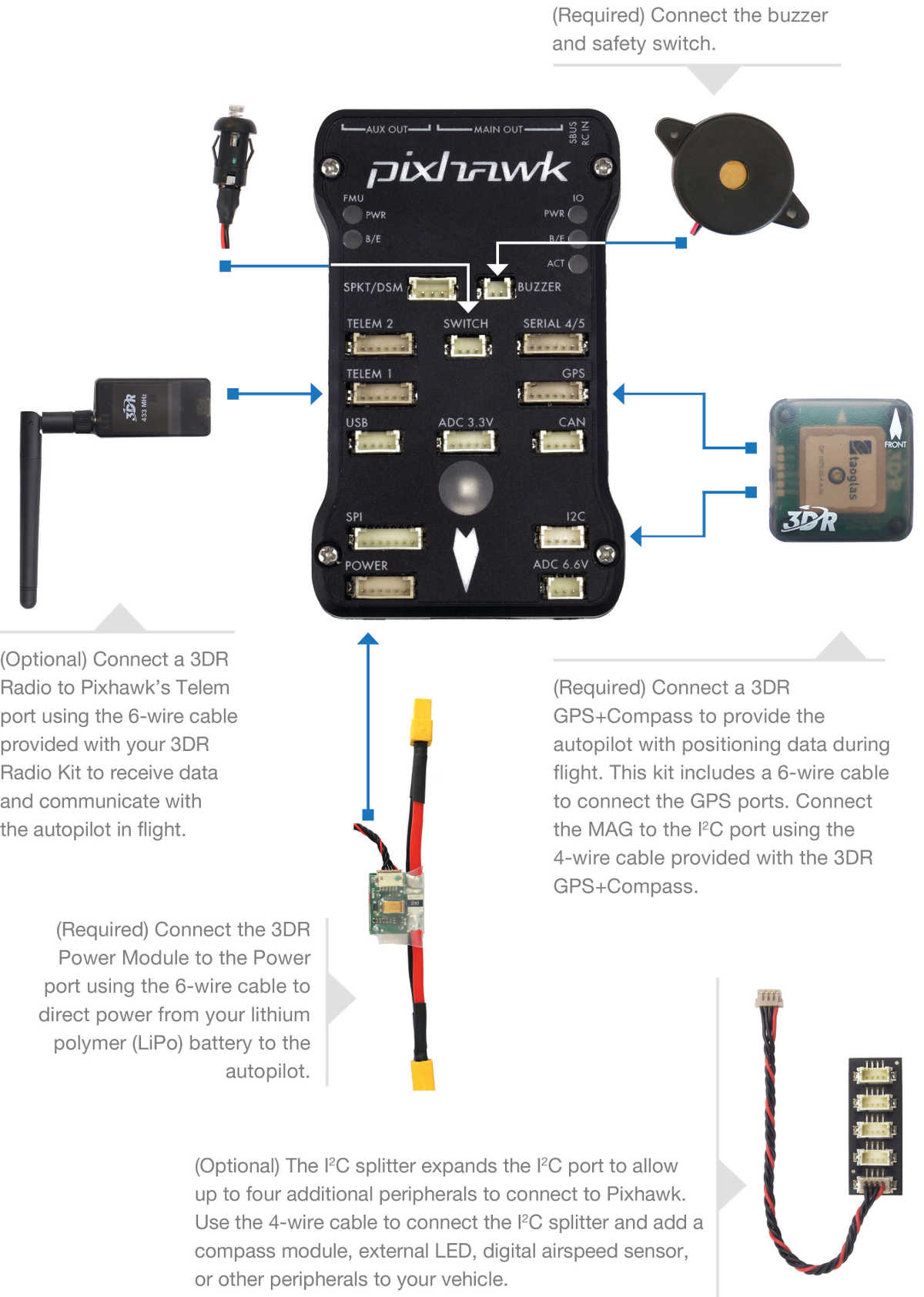
Copter users should also see the Advanced Pixhawk Quadcopter Wiring Chart.
Power Pixhawk
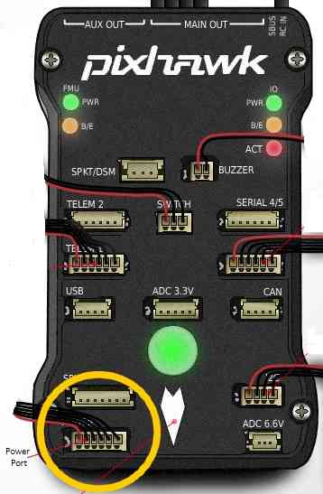
Pixhawk is typically powered via its “power” port, as shown in the picture below. The power port simultaneously powers Pixhawk and reads voltage and current analog measurements produced by an optional power module. Information about powering the Pixhawk can be found in the topic Powering the Pixhawk.
Note that powering Pixhawk does not power its servo rail. That is a separate supply, discussed under Connect Motors below.
Connect remote control inputs
Pixhawk is compatible with
PPM-Sum receivers
SBus receivers
IBUS receivers
For traditional single-wire-per-channel (PWM) receivers a PPM encoder can be used to convert the receiver outputs to PPM-SUM.
Tip
Information about compatible receivers and how they are connected can be found in Radio Control Systems
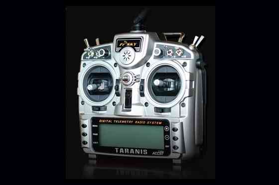
FRSky Taranis Transmitter
Connect buzzer and safety switch
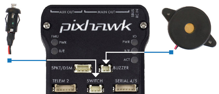
The buzzer and safety switch button are mandatory for Pixhawk. Connect to the BUZZER and SWITCH ports as shown.
Warning
Mount the beeper at least 5cm away from the flight controller or the noise may upset the accelerometers.
3DR GPS+Compass
The 3DR UBlox GPS + Compass Module is the recommended GPS for Pixhawk on ArduPilot. The GPS ports are connected with the six-position DF13 cable, and the MAG port is connected to the I2C port with the four-position DF13 cable.
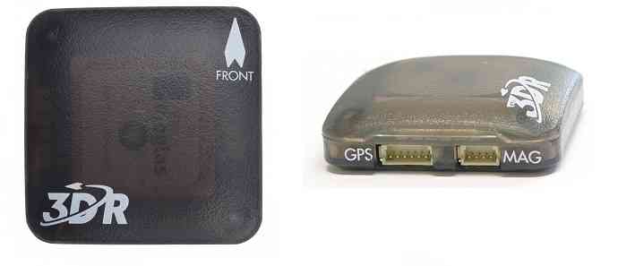
3DR UBlox GPS + Compass Module
The topic 3DR UBlox GPS + Compass Module shows how to connect to Pixhawk and include additional configuration and mounting information.
Connect Motors
Warning
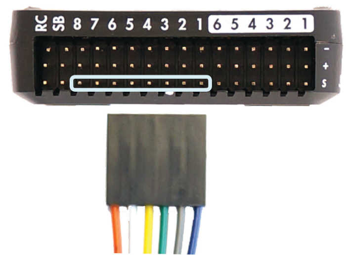
Pixhawk does not supply power to the servo rail - the MAIN OUT pins carry the signal only. ESCs draw their power from the battery, so multicopter motors will run with just the signal and ground wires connected. Servos will not: a plane’s control surfaces, a rover’s steering or a gimbal will not move until the rail itself is powered, normally from an ESC’s BEC or from a separate BEC.
Always connect the ground wire alongside an ESC’s signal wire. A signal wire must never be left floating without its ground reference.
Feed the rail from a single source. Where several ESCs each have a BEC, leave the power (red) wire connected on only one of them and remove it from the rest. Two supplies wired onto the rail in parallel will fight each other, and some BECs oscillate when driven that way, producing switching noise that can interfere with GPS and RC reception. See General wiring recommendations for the detail, and for how to combine sources properly if you do want a redundant supply.
Note
How much voltage the servo rail will tolerate, and whether it can also power the autopilot, differs between boards. Always check your board’s own page before wiring the rail.
On the original Pixhawk the servo rail is one of three power inputs, so it can power or back up the board. But it is dangerous to power Pixhawk only from the rail: a digital servo can drive the rail above 5.7V, at which point the power selector drops the input, the FMU loses power and the board reboots. Losing the FMU in flight means losing the aircraft. See Powering the Pixhawk.
Most current autopilots do not work this way. Their servo rail is isolated and does not power the autopilot at all, and many accept a far higher rail voltage - up to 36V on some boards - to drive high-voltage servos.
For Copter see Connect ESCs and Motors.
In overview, for copters connect each signal wire from the PDB to the main output signal (S) pins by motor number:
Pin 1 = Motor 1 - - Pin 5 = Motor 5
Pin 2 = Motor 2 - - Pin 6 = Motor 6
Pin 3 = Motor 3 - - Pin 7 = Motor 7
Pin 4 = Motor 4 - - Pin 8 = Motor 8
Connect other peripherals
Depending on your hardware there may be any number of other peripherals attached, including sensors, cameras, grippers etc. These can be found as sub-pages of the topic Optional Hardware.
Information about connecting these peripherals to Pixhawk is found in the respective pages.