ThePeach FCC-R1
Specifications
- Processor
STM32F427VIT6: 32bit ARM Cortex-M4, 168 MHz 256 KB RAM 2 MB Flash memory
IO Processor: STM32F100C8T6: ARM Cortex-M3, 32bit ARM Cortex-M3, 24 MHz, 8KB SRAM
- On-board Sensors
Accel/Gyro: ICM-20602
Accel/Gyro/Mag: MPU-9250
Barometer: MS5611
- Interfaces
8+5 PWM output (8 from IO, 6 from FMU)
Spektrum DSM / DSM2 / DSM-X Satellite compatible input
Futaba S.BUS compatible input and output
PPM sum signal input
Analogue / PWM RSSI input
S.Bus servo output
Safety switch/LED
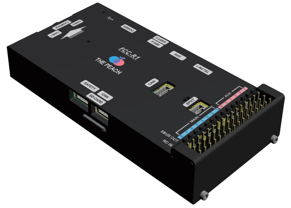
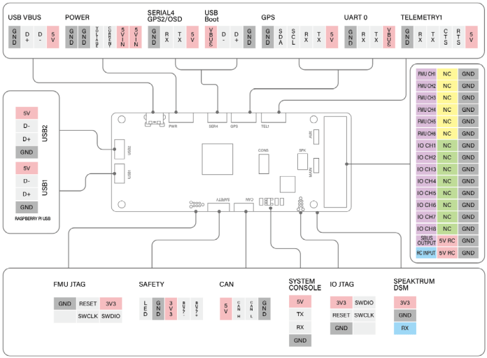
4x UART Ports: TELEM1, TELEM2(Raspberry Pi CM3+), GPS, SERIAL4
1x I2C Ports: GPS
1x CAN bus
Analog inputs for voltage / Current of 1 battery
- Interfaces For Raspberry Pi CM3+
VBUS
DDR2 Connector: Raspberry Pi CM3+
1x UART
2x USB
1x Raspberry Pi Camera
- Mechanical
Dimensions: 49.2 x 101 x 18.2mm
Weight: 100g
- Voltage Ratings
POWER input (5V to 5.5V)
USB Input (4.75V to 5.25V)
note:
The output power rails FMU PWM OUT and I/O PWM OUT do not power the autopilot board (and are not powered by it). You must supply power to one of POWER or USB or the board will be unpowered.
The USB do not power the Raspberry Pi CM3+. You must supply power to POWER or the Raspberry Pi CM3+ will be unpowered.
UART Mapping
SERIAL0 -> USB
SERIAL1 -> USART2 (TELEM1, RTS/CTS pins) DMA-enabled
SERIAL2 -> USART3 (TELEM2, RTS/CTS pins) DMA-enabled,Connected Raspberry Pi CM3+
SERIAL3 -> UART4 (GPS1)
SERIAL3 -> UART4 (GPS1) DMA-enabled
SERIAL4 -> UART8 (GPS2) TX only DMA-enabled
SERIAL5 -> UART7 (Debug)
Serial port protocols (Telem, GPS, etc.) can be adjusted to personal preferences using the SERIALx_PROTOCOL parameter.
RC Input
The RCIN pin, which by default is mapped to timer input, can be used for all ArduPilot supported receiver protocols, except CRSF/ELRS and SRXL2 which require a true UART connection. However, Fport, when connected in this manner, will only provide RC without telemetry
To allow CRSF and embedded telemetry available in Fport, CRSF, and SRXL2 receivers, a full UART, such as SERIAL4(UART8) would need to be used for receiver connections. Below are setups using UART8. SERIAL4_PROTOCOL should be set to “23”.
Fport would require SERIAL4_OPTIONS be set to”15”
CRSF would require SERIAL4_OPTIONS be set to “0”
SRXL2 would require SERIAL4_OPTIONS be set to “4” and connects only the UART8 TX pin.
Any UART can be used for RC system connections in ArduPilot also, and is compatible with all protocols except PPM. See Radio Control Systems for details.
PWM Output
The ThePeach FCC-R1 supports up to 14 PWM outputs. All outputs support all normal PWM output formats.
The 6 FMU PWM (AUX) outputs are in 2 groups and also support DShot:
AUX 1, 2, 3 and 4 in group1
AUX 5 and 6 in group2
FMU outputs within the same group need to use the same output rate and protocol. If any output in a group uses DShot then all channels in that group need to use DShot.
Battery Monitoring
The board has 1 dedicated power monitor port with a pin connector. It is intended for use with the Analog power monitor supplied with the autopilot.
Compass
The ThePeach FCC-R1 has a built-in MPU9250 compass. Due to potential interference the autopilot is usually used with an external I2C compass as part of a GPS/Compass combination.
GPIOs
The 6 AUX outputs can be used as GPIOs (relays, buttons, RPM etc). To use them you need to set the output’s SERVOx_FUNTION to -1. See GPIOs page for more information
The numburing of the GPIOs for PIN variables in Ardupilot is:
AUX 1 50
AUX 2 51
AUX 3 52
AUX 4 53
AUX 5 54
AUX 6 55
Connectors
Loading Firmware
The board comes pre-installed with an ArduPilot compatible bootloader, allowing the loading of xxxxxx.apj firmware files with any ArduPilot compatible ground station.
Firmware for this board can be found here in sub-folders labeled “thepeach-r1”.
Where to Buy
Order from ThePeach