Building a Blimp
Building an Indoor finned Blimp
This type of blimp has four flapping fins driven by servos, which combine to provide X, Y, Z and Yaw control, while pendulum stability keeps roll and pitch close to zero.
These instructions are specifically for building a ~50cm diameter spherical blimp, although the sizes of parts can be adapted to build bigger blimps of the same type. This size of balloon will give about 50g of lift (excluding the lift required to lift the envelope itself).
Parts
Autopilot. This is the most complex part to find due to the very specific limitations. Due to the very low weight limit, none of the usual high-end autopilots are suitable, as they are much too heavy. The most suitable autopilots are the single-pcb type, such as the Matek F405-STD, which has had extensive testing with Blimp. It includes a microSD card slot and has good rc input and pwm outputs, which make it highly convenient, especially for development, but it still weighs 9 grams. Using a autopilot like this one which is designed to be powered from 5v rather than battery power is optimal, as autopilots that can be powered from battery usually require a minimum of 2S or 3S voltage, and the only servos small enough for this application can only run from 5v or less. There are some other autopilots available which weigh closer to 2-3 grams which would allow for more payload, although they generally have a dataflash chip instead of a microSD card slot (among other things) which is less convenient. This page gives some further information on what to consider in an ArduPilot autopilot.
Envelope to be filled with helium. The ~50 cm spherical foil party balloons work quite well for indoor use.
Four servos. The 1.7g micro servos are suggested.
Approx. 1-2mm thick sheets of balsa wood and plastic freezer bags for making the fins.
Very thin wires.
Battery. For this size of blimp, 150-300mAh 1S is generally most suitable.
Telemetry module. Unfortunately, the usual SiK telemetry modules are too heavy for this case. The smallest versions of the ESP8266 modules, such as the ESP-01 or ESP-07 are most suitable.
For RC control, again, finding a tiny RC receiver is necessary. The OrangeRx Nano DSM2/DSMX receiver is a great option as it only weighs 0.5 grams.
A 5V Step-Up Voltage Regulator for powering the autopilot from 1S. In tests it was found that the autopilot could be powered from the battery directly, however it browned out at around 3.6v (i.e. rebooted repeatedly due to low voltage) which means you would not be able to use the full battery capacity if you do not use one of these.
Wiring
The 5v step-up converter is added to allow the autopilot to run from a 1S battery. Its input comes from directly from the battery, and the output goes to the autopilot’s 5v pin.
If a MatekF405-STD autopilot is used, the RC receiver is powered from one of the 4.5v pins on the autopilot. Otherwise, any 5v pin on the board can be used. This is because the 4.5v pins are also powered when the autopilot is powered via USB, thus allowing setup and RC calibration without a battery connected. The receiver’s output is connected to the RX2 input of the autopilot.
The Wi-Fi module is powered directly from the battery. Its TX and RX pins are connected to the RX3 and TX3 pins on the autopilot.
The four servos are connected to four of the servo/motor outputs on the board, and are powered directly from the battery.
Building the Fins
Cut 8 strips from the sheet of balsa wood, measuring 185 mm by 5 mm. Make sure to cut along the grain.
Use super glue to glue the ends of two strips at 90 degrees to each other, forming a right-angled triangle.
Repeat this with the other 6 strips.
Cut triangles out of the plastic of the same size as the wood frames.
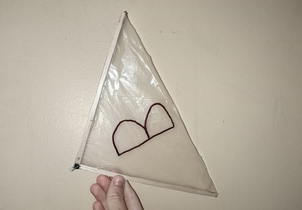
Glue the plastic to the the wood frames. The hypotenuse edge will be left loose. Try to keep the plastic pulled flat while you glue, but without warping the wood frame.
Glue the 90 deg attachment points to the corner of the triangle where you glued the two strips together.
See the photo below for an example:
Putting it all together
The servos need to be attached in a specific orientation in order for the flapping with offset to work correctly. These are as follows, orientation is looking directly at the servo and balloon from 90 degrees:
The front and back servos are oriented sideways so that the fin will flap up and down when the servo moves.
Front servo: output gear at the top left of the servo body.
Back servo: output gear at the top right of the servo body.
The left and right servos are oriented upright so that the fin will flap left to right when the servo moves.
Left servo: output gear at the top right of the servo body.
Right servo: output gear at the top left of the servo body.
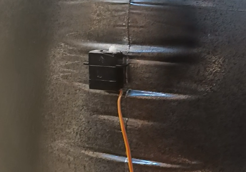
See the photos below for the orientation of each servo:
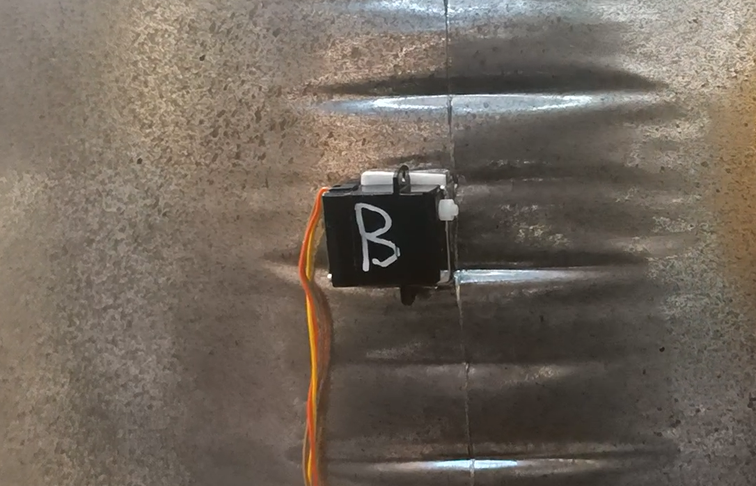
Back fin servo |
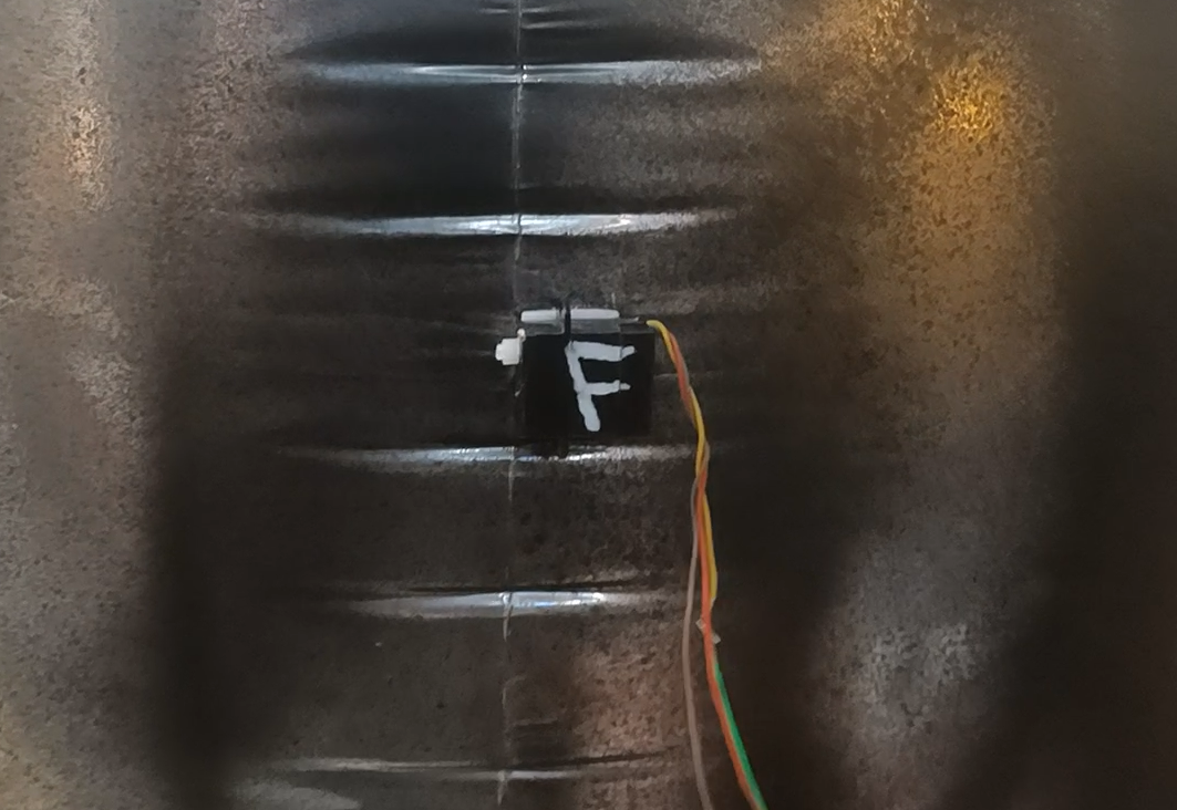
Front fin servo | |
Left fin servo |
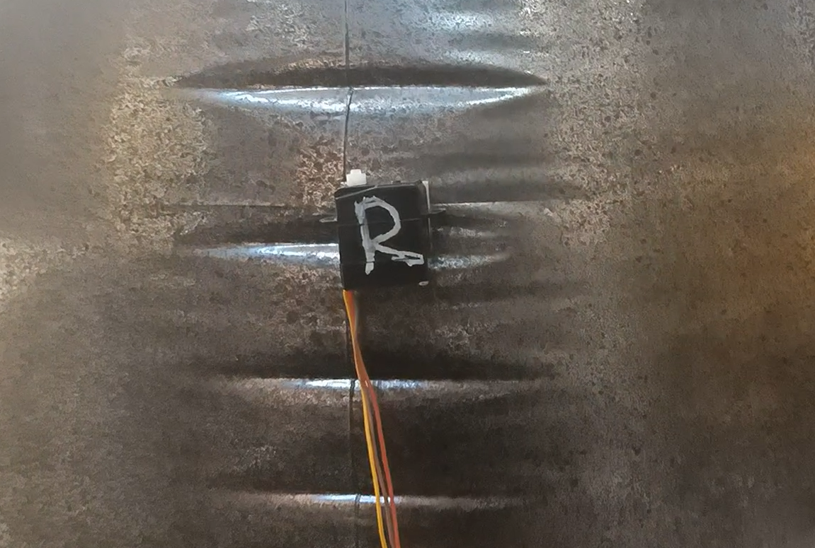
Right fin servo |
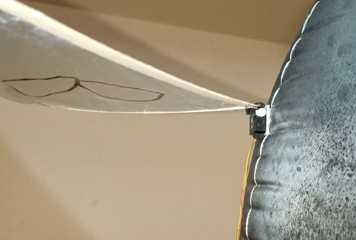
Now the servo horns can be glued onto the fins to allow for attaching to the servos. Take care when gluing them so that there is enough clearance between the fin and the servo’s body to allow for its full range of motion. With the fins and servos in the photos, it was best to glue the servo horns such that when attached to the servo, the wood of the fin is on the side of the servo where the output gear is closer to the edge.