PocketBeagle 2
PocketBeagle 2 (PB2) is an upgraded version of the popular PocketBeagle, designed as an ultra-compact, low-cost, and powerful single-board computer (SBC). Targeted at developers, students, and hobbyists, PocketBeagle 2 retains the simplicity and flexibility of its predecessor while delivering enhanced performance and expanded features to support modern development needs. PocketBeagle 2 is ideal for creating IoT devices, robotics projects, and educational applications. Its small form factor and low power consumption make it a versatile platform for embedded development, whether prototyping or deploying at scale.
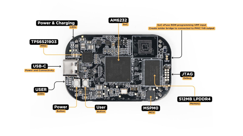
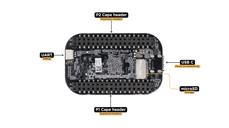
PocketBeagle 2 is based on Texas Instruments AM6254 SoC. Its multiple A53 cores can provide higher performance than the classic PocketBeagle. The new design comes with pre-soldered headers, a 3-pin JST-SH 1.00mm UART debug port, a USB-C port, Texas Instruments MSPM0L1105 Cortex-M0+ MCU for ADC, 512MB RAM, and a LiPo Battery charger.
Note
For now, the only supported version is Rev A0 shipped with AM6232 (dual-core A53, no GPU).
Specifications
Processor
Texas Instruments AM6232 SoC
Multicore 64-bit Arm Cortex-A53 microprocessor subsystem at up to 1.4 GHz
Each A53 Core has 32KB L1 DCache with SECDED ECC and 32KB L1 ICache with Parity protection
Single-core Arm® Cortex®-M4F MCU at up to 400MHz
Dual-core Programmable Real-Time Unit Subsystem (PRUSS) running up to 333 MHz
512MB LPDDR4 3200MHz
OS
Linux (Debian)
Note
For now, the only supported version is Rev A0 shipped with AM6232 (dual-core A53, no GPU). Rev A1 should be working but haven’t been tested yet
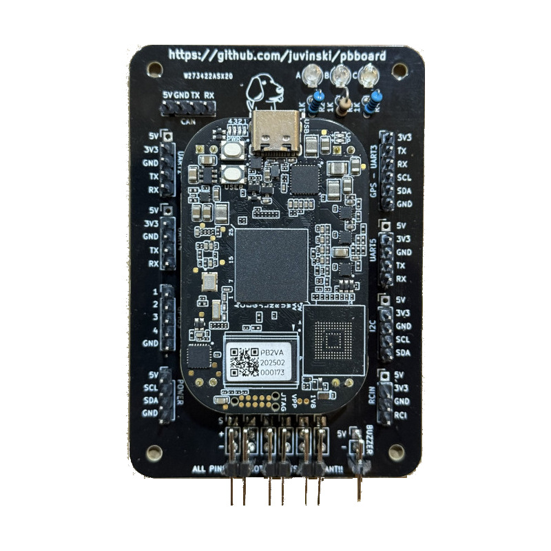
DIY Cape
The board and all information about the board can be found in the github here.
Schematic
The schematic can be found in this link.
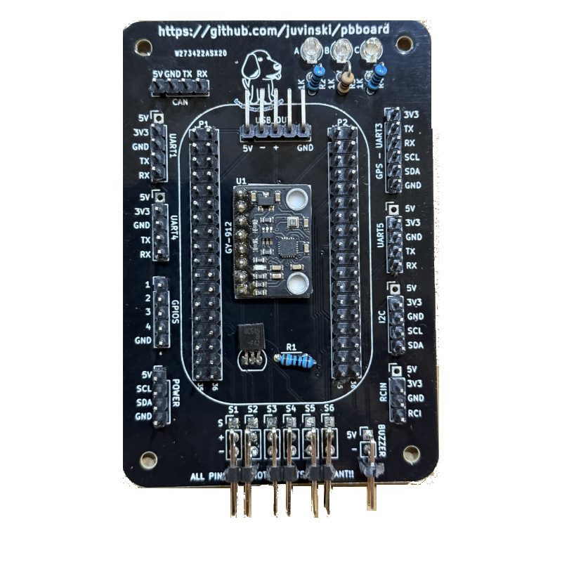
Cape Components
1 IMU GY-912
4 Resistors 1KΩ
3 Led Red, Blue and Green color
1 BC548 NPN Transistor
1 I2C Digital Power Module/Monitor
6 Pin header 1 x 5 straight
3 Pin header 1 x 4 straight
1 Pin header 1 x 6 straight
6 Pin header 1 x 3 straight or 90°
1 Pin header 1 x 2 straight
1 Pin header female 1 x 8 - optional
Board Details
4 UARTs - One have the I2C to be used with a GPS + Compass
2 I2Cs - One is under the Power header
4 GPIO pins with GND
6 Outputs
Buzzer output for an Active buzzer
Quick Start
Preparing SD Card with linux for PB2
Download the linux image from https://files.beagle.cc/file/beagleboard-public-2021/images/pocketbeagle2-debian-13-base-v6.12-arm64-2025-09-05-8gb.img.xz used in this example). You can download images from from https://www.beagleboard.org/distros or you can use the BeagleBoard Imaging Utility.
Flash image onto SD card.
Setting default user and password
The default user and password for the debian is debian and default password is temppwd. To change the defaults, insert the SDCard in your computer and in the BOOT partition open the sysconf.txt. Then look for the user_name and user_password, uncomment the line and set the values.
Using the BeagleBoard Imaging Utility you will see a button Edit where you can change the default user and password.
Booting and first access
Insert SD card in PocketBeagle 2 and power up using a suitable USB cable at the USB C connector.
Connect via SSH (ssh <your username>@192.168.7.2) and insert your password.
Configuring the Device Tree Overlay
To run ardupilot in the PocketBeagle 2, you need to configure a device tree overlay.
Instructions
ssh debian@192.168.7.2 #case you changed the default user, user yours
sudo su -
vi /boot/firmware/extlinux/extlinux.conf
#Search for a line with "label microSD (default)"
#replace the commented line #fdtoverlays
fdtoverlays /overlays/k3-am62-pocketbeagle2-ardupilot-cape.dtbo
Reboot the board to load the device tree overlay.
reboot
To check if the device tree is loaded, after the reboot
ssh debian@192.168.7.2 #replace debian with your username of the default - temppwd

ls /dev/spi*
# example output
/dev/spidev0.0  /dev/spidev0.1

/dev/spi:
0.0  0.1

ls /dev/i2c-*
# example output
/dev/i2c-0  /dev/i2c-2  /dev/i2c-3  /dev/i2c-4
Compiling spidev_test
We are facing an issue with the IMU SPI initialisation. To fix, you need to download and compile the spidev_test program and run prior ardupilot.
Instructions
cd~
wget https://raw.githubusercontent.com/torvalds/linux/refs/heads/master/tools/spi/spidev_test.c
sudo gcc spidev_test.c -o /usr/local/bin/spidev_test
Compiling ArduPilot
We recommend to use cross-compilation(5-10 minutes) instead direct compilation in the PB2 board(time > 1 hour)
To build your own firmware, see the instructions on setting up a build environment and compiling the source code: Building the Code
You need to install gcc-aarch64-linux-gnu :
sudo apt-get update && apt-get install gcc-aarch64-linux-gnu
PocketBeagle2 Instructions
./waf configure --board=pocket2

#**To compile all vehicles**
./waf build

#**To compile copter**
./waf copter

#**To compile plane**
./waf plane

#**To compile rover**
./waf rover

#**To compile sub**
./waf sub

#**To compile examples**
./waf examples
Alternatively there are other possible sources like the https://custom.ardupilot.org/ build server
To copy ardupilot files to the your PocketBeagle 2: From your ardupilot directory :
scp -qpr build/pocket2/bin/* <your username>@192.168.7.2:/home/<your username>/ardupilot/
Setting up ArduPilot
The following instructions show how to setup ArduPlane. It is the same for other vehicle types just replace copter by e.g. plane etc. It is also possible to setup multiple vehicle types on the same system.
First let’s create a configuration file
sudoedit /etc/default/ardupilot
#inside the file add the following lines
TELEM1="--serial1 /dev/ttyS1"
TELEM2="--serial0 udp:<target IP address>:14550"
GPS="--serial3 /dev/ttyS3"
RANGEFINDER="--serial5 /dev/ttyS5"
#Removing any empty space in the beginning of the lines
#Press CTRL+X then press enter
Now, let’s create an auxiliary script to setting some linux stuffs
sudoedit /usr/local/bin/prep_ardu.sh
#inside the file add the following lines

#!/usr/bin/bash
#This is needed to initialisation the SPI Bus for the IMU
/usr/bin/spidev_test -D /dev/spidev0.0 -H -O -s 1000000 -v -p "\x80\x00"

#Removing any empty space in the beginning of the lines
#Press CTRL+X then press enter
sudo chmod +x /usr/local/bin/prep_ardu.sh
Create an empty service file so that ardupilot automatically starts on boot and runs in the background:
sudo nano /lib/systemd/system/arducopter.service
Paste following text. And replace <target IP address> with the IP address of the telemetry receiving computer:
[Unit]
Description=ArduCopter Service
After=networking.service
StartLimitIntervalSec=0
Conflicts=arduplane.service ardurover.service antennatracker.service

[Service]
EnvironmentFile=/etc/default/ardupilot
ExecStartPre=-/usr/local/bin/prep_ardu.sh
ExecStart=/home/<your username>/ardupilot/arducopter $TELEM1 $TELEM2 $GPS $RANGEFINDER
Restart=on-failure
RestartSec=1

[Install]
WantedBy=multi-user.target
Enabling arducopter service
sudo systemctl enable arducopter.service
sudo reboot
Checking arducopter
ssh debian@192.168.7.2 #replace debian with your username of the default - temppwd
ps -a|grep arducopter
618 pts/2    00:00:03 arducopter
#the first number and the timer counter will be different.
Using DSHOT
You can use DSHOT 600 protocol as RC output. For now, the DSHOT support doesn’t provide bidirectional - so no telemetry, and all 6 outputs will output DSHOT, you cannot mix DSHOT and PWM protocols.
Using CAN
Software:
You need to enable and up the SocketCAN network interface, in our case we added the following lines at the prep_ardu.sh script.
/usr/bin/ip link set can0 type can bitrate 1000000
/usr/sbin/ifconfig can0 up
Hardware:
To use CAN, you need a CAN transceiver like TJA1051. There is one output in the DIY board to connect the transceiver.
USB OTG connection
The board was tested with USB C and MicroUSB connector for otg connection, connecting 5 volts, + and - should be connected to the D+ and D- pins and GND pins.
Errors and known issues
The SPI BUS initialisation is the only main issue related to Ardupilot. We recommend to freeze (not update) the linux kernel. Beside all working and support from Mr, RobertCNelson, we noted sometimes a new kernel can add problems with the SPI bus. This can be noticed when you run ardupilot and receive messages of the IMU RESET in the GCS messages panel.
Flying video
First flight :)
February 2026