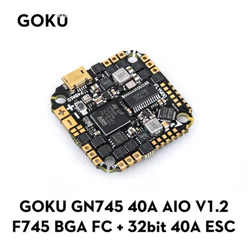
Flywoo GOKU GN 745 AIO with 40A ESC/45A ESC/ Nano
The Flywoo GOKU GN 745 AIO is an autopilot produced by [Flywoo](https://flywoo.net/).
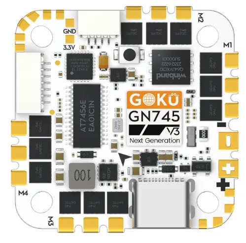
The Flywoo GOKU GN 745 45A AIO V3 is an updated version of the above, with 45A ESC.
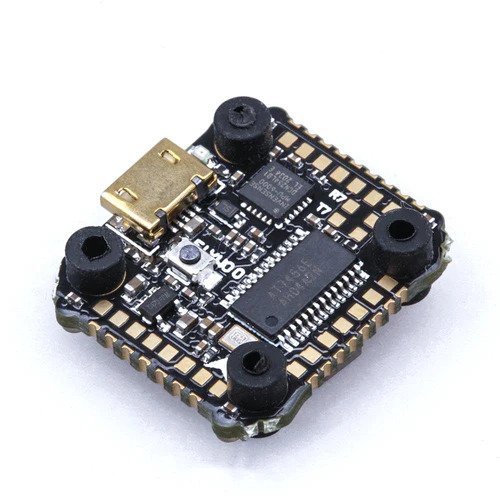
The Nano version is a smaller reduced feature set version
Where To Buy
Specifications
Processor
STM32F745VG ARM (216MHz), 1MB Flash
Integrated 4 output, BLHeli-32 40A ESC (AIO V1.2) or BLHeli-32 45A ESC (AIO V3)
Onbord 8 Mbytes (versions 1.0 and 1.2) or 16 MBytes (version 3) for Blackbox logging
Sensors
InvenSense MPU6000 IMU or ICM42668P (accel, gyro)
BMP280 barometer
Voltage & 100A Current sensor (AIO version only)
Power
7.4V ~ 25V DC input power (4S MAX for Nano version)
5V 2A BEC for peripherals
9V 1.5A BEC for video (no 9V rail on V3 AIO)
Interfaces
7x UARTS
10x PWM outputs, first 4 are internally connected to 4in1 BLHeli32 ESC (AM32 in V3).
I2C port for external compass, airspeed sensor, etc.
USB port
Camera input/ VTX output
Built-in OSD
Size and Dimensions AIO
33.5mm x 33.5mm (25.6 x 25.6mm mount pattern)
8.5g for V1.2, 9.4g for V3
Size and Dimensions Nano
22mm x 23.5mm (16mm x16mm mount pattern)
2.3g
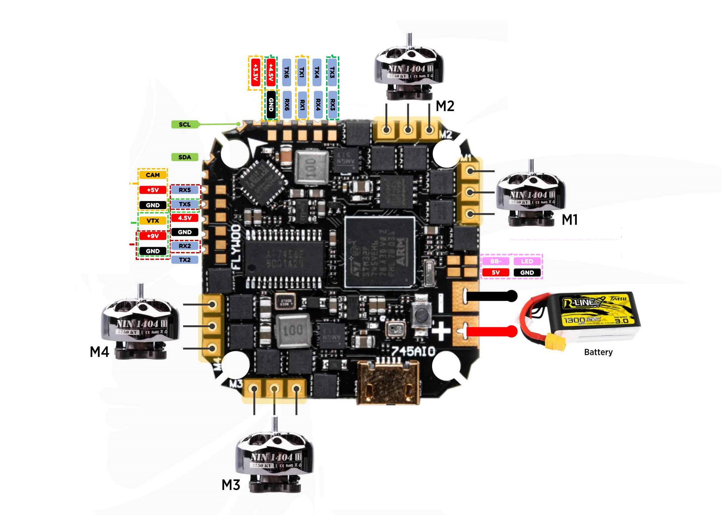
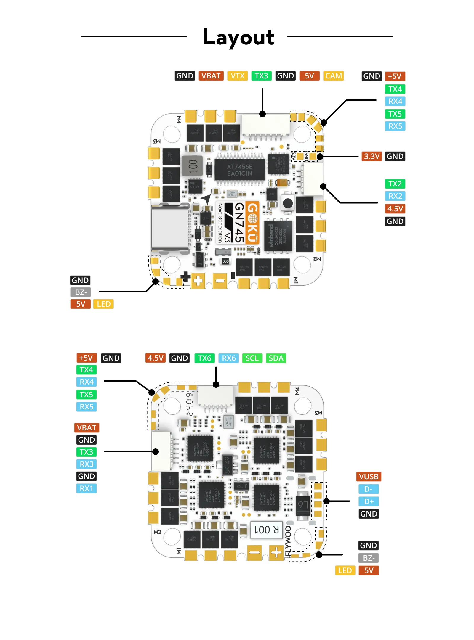
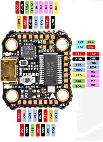
Pinouts
AIO V1.2
AIO V3
Nano
Default UART order
SERIAL0 = console = USB
SERIAL1 = Telemetry1 = USART1 (RX pin only in AIO V3)
SERIAL2 = Telemetry2 = USART2
SERIAL3 = RC Input = USART3
SERIAL4 = USER = USART4
SERIAL5 = USER = UART5
SERIAL6 = GPS = USART6
SERIAL7 = ESC Telem = UART7 (RX tied to ESC telemetry) See blheli32-esc-telemetry
UART3 supports RX and TX DMA. UART1, UART2, UART4, and UART6 supports TX DMA. UART5 and UART7 do not support DMA. Serial port protocols (Telem, GPS, etc.) can be adjusted to personal preferences.
RC Input
RC input is configured on the RX3 (UART3_RX) pin. It supports all RC protocols except PPM. See Radio Control Systems for details for a specific RC system. SERIAL3_PROTOCOL is set to “23”, by default, to enable this.
SBUS/DSM/SRXL connects to the RX3 pin but SBUS requires that the SERIAL3_OPTIONS be set to “3”.
FPort requires connection to TX3 and SERIAL3_OPTIONS be set to “7”.
CRSF also requires a TX3 connection, in addition to RX3, and automatically provides telemetry. Set SERIAL3_OPTIONS to “0”.
SRXL2 requires a connection to TX6 and automatically provides telemetry. Set SERIAL3_OPTIONS to “4”.
Any UART can be used for RC system connections in ArduPilot also, and is compatible with all protocols except PPM. See Radio Control Systems for details.
Note
In version 3, the connector intended for RC input is on the UART2, so the default protocol will need to be changed for SERIAL 2 to “23” and SERIAL 3 protocol changed to something else.
Note
the V3 AIO moves this to UART2.
PWM Output
The GOKU GN 745 AIO supports up to 8 PWM outputs. The pads for motor output ESC1 to ESC4 on the above diagram are the first 4 outputs, there are four additional pads for PWM 5-8. All 8 outputs support DShot as well as all PWM types.
The Nano version has 4 esc signals, current and voltage sense inputs on an external connector. The remaining outputs are on solder pads.
Note
for users migrating from BetaflightX quads using the Nano, the first four outputs M1-M4 have been configured for use with existing motor wiring using these default parameters:
FRAME_CLASS = 1 (Quad)
FRAME_TYPE = 12 (BetaFlightX)
The PWM are in 5 groups: 1/2/7/8, 3/4, 5, 6
Channels within the same group need to use the same output rate. If any channel in a group uses DShot then all channels in the group need to use DShot. PWM 1-4 support bidirectional DShot.
Neopixel Output
The LED pin is PWM output 9 and is default setup for use with a NeoPixel 4 led string for notifications.
Battery Monitor
The board has a built-in voltage and current sensors.
The correct battery monitor parameters are:
BATT_MONITOR = 4
BATT_VOLT_PIN = 13
BATT_VOLT_MULT ~ 10.9
BATT_CURR_PIN = 12
BATT_AMP_PERVLT ~ 21 (when using AIO version 1.2) (or approx 14 for AIO version 3)
These are set by default in the firmware and shouldn’t need to be adjusted (apart from for V3).
Compass
The GOKU GN 745 AIO does not have a builtin compass but it does have an external I2C connector.
IMU
The AIO V3 has its IMU at a different orientation to V1.2. This means AHRS_ORIENTATION = 5 (Yaw225) needs to be set for V3.
Loading ArduPilot onto the board
Initial firmware load can be done with DFU by plugging in USB with the bootloader button pressed. Then you should load the “with_bl.hex” firmware, using your favourite DFU loading tool.
Once the initial firmware is loaded you can update the firmware using any ArduPilot ground station software. Updates should be done with the xxxxxxxxxx.apj firmware files.
Firmware
Firmware for this board can be found here in sub-folders labeled “FlywooF745” for the AIO or “FlywooF745Nano” for the Nano version.