Tuning Navigation
This page describes how to tune the Navigation control including “S-Curves” and the “Position controller”. The lower level speed and turn rate controllers should be tuned before attempting to tune this controller.
S-Curves and the position controller are used all the autonomous modes including Auto, Guided, RTL and SmartRTL.
S-Curves
S-Curves are used to plan a smooth path that brings the vehicle close to each waypoint while not exceeding speed or acceleration limits. The resulting path includes continuous position and 2D velocity targets.
Factors affecting the path include:
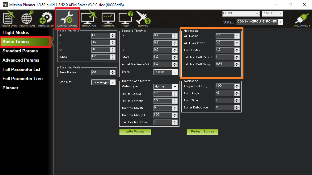
The vehicle will cut the corners but will always try to pass within WP_RADIUS or TURN_RADIUS (whichever is larger) of each waypoint
The vehicle will cut the corners more at higher speeds
The vehicle will cut the corners more if the maximum accelerations are reduced (e.g. the lowest of ATC_ACCEL_MAX, ATC_DECEL_MAX and TURN_MAX_G * 9.81)
The vehicle will slow down in the corners if necessary to pass within WP_RADIUS of the waypoint without exceeding the maximum accelerations (e.g. the lowest of ATC_ACCEL_MAX, ATC_DECEL_MAX and TURN_MAX_G * 9.81)
Placing waypoints close together may lead to the vehicle travelling slowly
Position Controller
The position controller is responsible for calculating the desired speed and turn rate so the vehicle follows the path between waypoints created by the S-Curves (see above). The desired speed and turn rate are then passed to the lower level controllers.
Method for tuning the position controller:
Connect the ground station to the vehicle using a telemetry radio
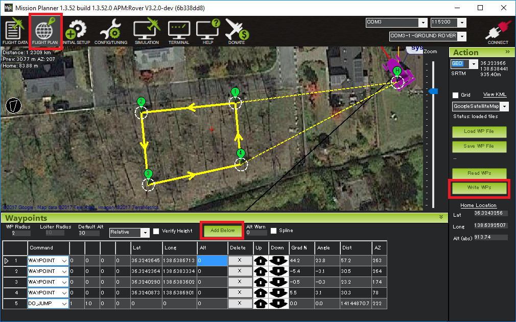
Create a rectangular or back-and-forth mission with long straight segments and upload to the vehicle
Arm the vehicle (in Manual or Hold) and then switch to Auto mode
Adjust these parameters to improve the vehicle’s tracking along the lines
These values normally do not need to be changed
PSC_POS_P should be left at 0.2 (the default). This converts the position error into a desired velocity. Higher values will lead to the vehicle trying to drive back to the line more quickly but if raised too high may lead to oscillation
PSC_VEL_FF should always be 0
PSC_VEL_IMAX should always be 1
PSC_VEL_FLTD, PSC_VEL_FLTE should be left at the default of 5 although small vehicle may benefit from higher values
It may also help to monitor the velocity controller PIDs in real-time
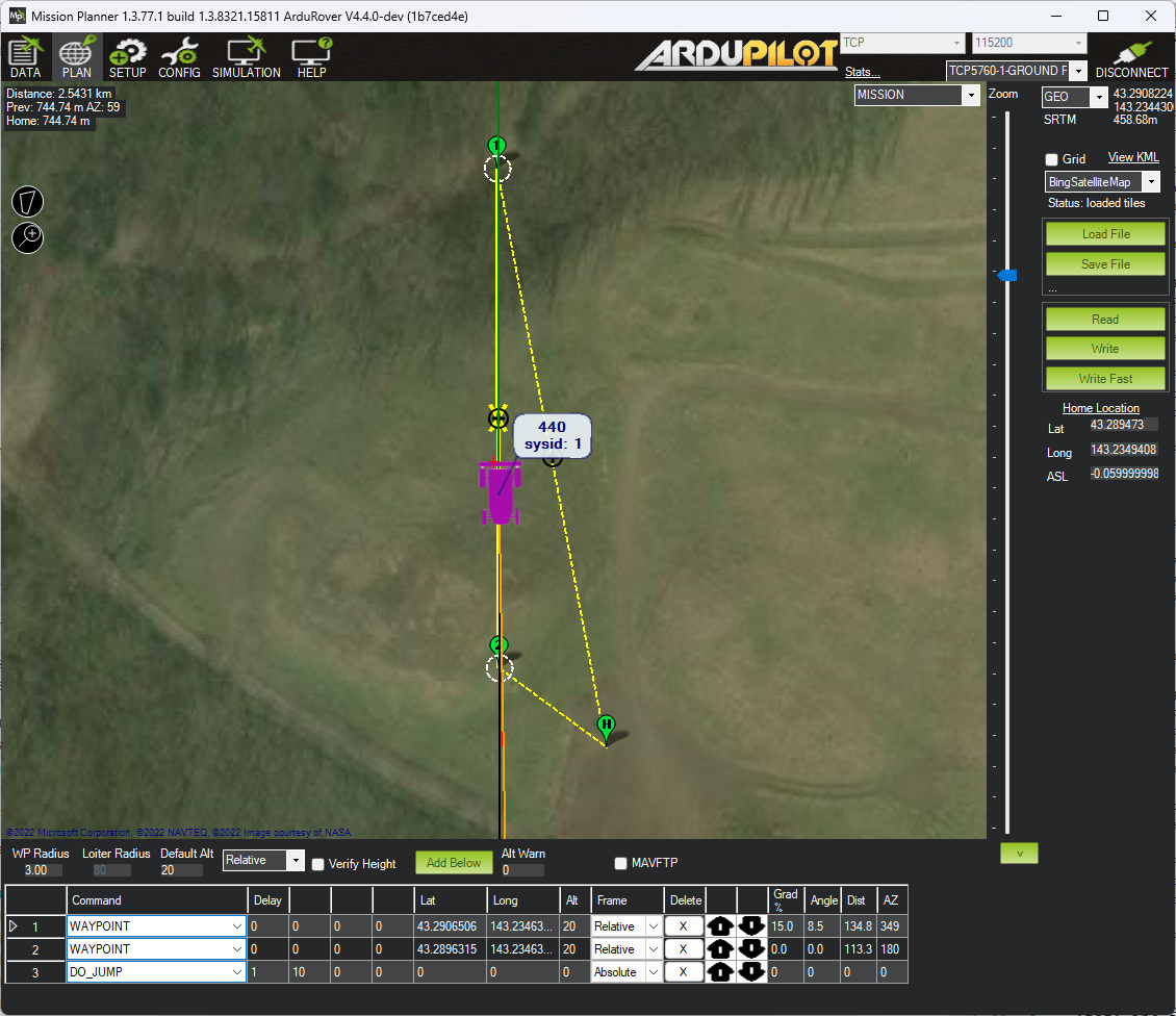
Ensure the mission has long straight segments aligned either North-South or West-East
Enable real time PID reporting of the position controller’s velocity controller
If the mission runs West-East set GCS_PID_MASK = 64 (Velocity North)
If the mission runs North-South set GCS_PID_MASK = 128 (Velocity East)
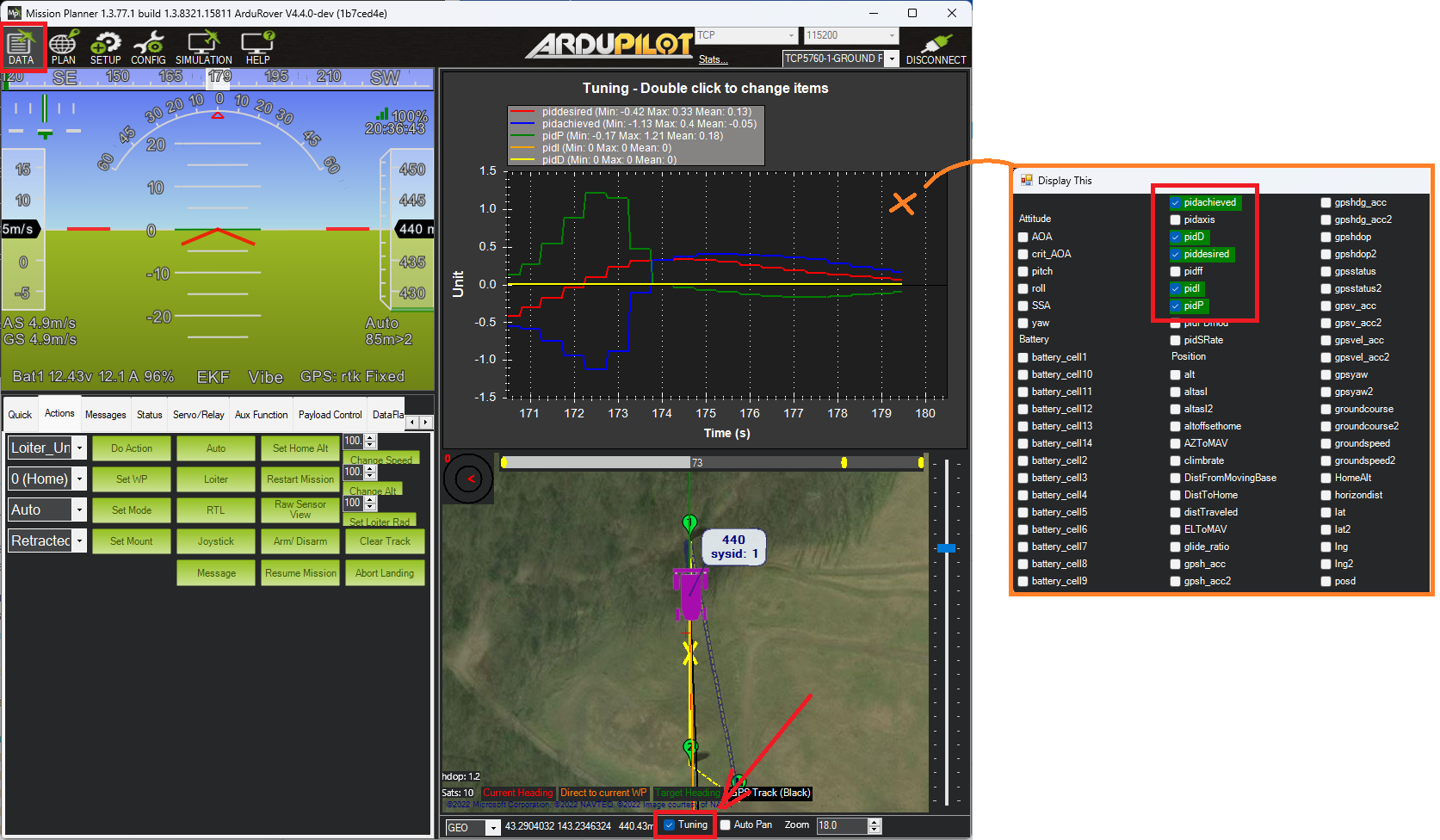
Display the real-time PID values on the ground station. If using MP, go to the Data screen, check the “Tuning” checkbox. Double click on the display area and select, “piddesired”, “pidachieved”, “pidP”, “pidI” and “pidD”
Other Parameters
How the Position Controller works
Compares the vehicle’s current location to the desired location and calculating a desired 2D velocity to close the gap
Compares the vehicle’s current velocity to the above velocity (aka position correction velocity) + the S-Curve provided velocity and calculating a desired 2D acceleration to reduce the error
The vehicle forward-back portion of position correction velocity + S-Curve velocity is the target forward speed
the lateral component of the 2D acceleration becomes the target turn rate