Extended Kalman Filter Navigation Overview and Tuning
Warning
IMPORTANT: This article is about EKF1 which has been removed from the codebase. It’s kept as a reference, as it has been the basis for EKF2 and EKF3. EKF3 is now the default.
This article describes the Extended Kalman Filter (EKF) algorithm used to estimate vehicle position, velocity and angular orientation based on rate gyroscopes, accelerometer, compass (magnetometer), GPS, airspeed and barometric pressure measurements. It includes both an overview of the algorithm and information about the available tuning parameters.
Overview
The availability of faster processors (like the one on Pixhawk) have enabled more advanced mathematical algorithms to be implemented to estimate the orientation, velocity and position of the flight vehicle. An Extended Kalman Filter (EKF) algorithm has been developed that uses rate gyroscopes, accelerometer, compass, GPS, airspeed and barometric pressure measurements to estimate the position, velocity and angular orientation of the flight vehicle. This algorithm is implemented in the AP_NavEKF2 and AP_NavEKF3 libraries and is based on initial work documented here: https://github.com/priseborough/InertialNav
The advantage of the EKF over the simpler complementary filter algorithms used by DCM and Copter’s Inertial Nav, is that by fusing all available measurements it is better able to reject measurements with significant errors so that the vehicle becomes less susceptible to faults that affect a single sensor.
Another feature of the EKF algorithm is that it is able to estimate offsets in the vehicle’s compass readings and also estimate the earth’s magnetic field for both plane and copter as well as rover applications. This makes it less sensitive to compass calibration errors than current DCM and INAV algorithms.
It also enables measurements from optional sensors such as optical flow and laser range finders to be used to assist navigation.
Theory
The EKF (Extended Kalman Filter) algorithm implemented, estimates a total of 22 states with the underlying equations derived using the following: https://github.com/priseborough/InertialNav/blob/master/derivations/GenerateEquations22states.m
The following is a greatly simplified non-mathematical description of how the filter works:
IMU angular rates are integrated to calculate the angular position
IMU accelerations are converted using the angular position from body X,Y,Z to earth North,East and Down axes and corrected for gravity
Accelerations are integrated to calculate the velocity
Velocity is integrated to calculate the position
This process from 1) to 4) is referred to as ‘State Prediction’. A ‘state’ is a variable we are trying to estimate like roll, pitch, yaw, height, wind speed, etc. The filter has other states besides position, velocity and angles that are assumed to change slowly. These include gyro biases, Z accelerometer bias, wind velocities, compass biases and the earth’s magnetic field. These other states aren’t modified directly by the ‘State Prediction’ step but can be modified by measurements as described later.
Estimated gyro and accelerometer noise (
EKF_GYRO_NOISEandEKF_ACC_NOISE) are used to estimate the growth in error in the angles, velocities and position calculated using IMU data. Making these parameters larger causes the filters error estimate to grow faster. If no corrections are made using other measurements (eg GPS), this error estimate will continue to grow. These estimated errors are captured in a large matrix called the ‘State Covariance Matrix’.Steps 1) to 5) are repeated every time we get new IMU data until a new measurement from another sensor is available.
If we had a perfect initial estimate, perfect IMU measurements and perfect calculations, then we could keep repeating 1) to 4) throughout the flight with no other calculations required. However, errors in the initial values, errors in the IMU measurements and rounding errors in our calculations mean that we can only go for a few seconds before the velocity and position errors become too large.
The Extended Kalman Filter algorithm provides us with a way of combining or fusing data from the IMU, GPS, compass, airspeed, barometer and other sensors to calculate a more accurate and reliable estimate of our position, velocity and angular orientation.
The following example describes how GPS horizontal position measurements are used, however the same principal applies to other measurement types (barometric altitude, GPS velocity, etc)
When a GPS measurement arrives, the filter calculates the difference between the predicted position from 4) and the position from the GPS. This difference is called an ‘Innovation’.
The ‘Innovation’ from 6), ‘State Covariance Matrix’ from 5), and the GPS measurement error specified by
EKF_POSNE_NOISEare combined to calculate a correction to each of the filter states. This is referred to as a ‘State Correction’.This is the clever part of the a Kalman Filter, as it is able to use knowledge of the correlation between different errors and different states to correct states other than the one being measured. For example GPS position measurements are able to correct errors in position, velocity, angles and gyro bias.
The amount of correction is controlled by the assumed ratio of the error in the states to the error in the measurements. This means if the filter thinks its own calculated position is more accurate than the GPS measurement, then the correction from the GPS measurement will be smaller. If it thinks its own calculated position is less accurate than the GPS measurement, then the correction from the GPS measurement will be larger. The assumed accuracy of the GPS measurement is controlled by the
EKF_POSNE_NOISE, parameter. MakingEKF_POSNE_NOISElarger causes the filter to think the GPS position is less accurate.Because we have now taken a measurement, the amount of uncertainty in each of the states that have been updated is reduced. The filter calculates the reduction in uncertainty due to the ‘State Correction’, updates the ‘State Covariance Matrix’ and returns to step 1)
Tuning Parameters
AHRS_EKF_USE
This should be set to 1 to enable use of the filter, or set to 0 to use the legacy algorithms. Be aware that both algorithms are running regardless of this parameter, and all the EKF data will be logged regardless, provided full rate AHRS data logging is enabled.
From Copter3.3 onwards the EKF has been enabled by default and this parameter is not available. Plane and Rover users can still elect to use the legacy algorithms.
EKF_ABIAS_PNOISE
This noise controls the growth of the vertical accelerometer bias state error estimate. Increasing it makes accelerometer bias estimation faster and noisier.
EKF_ACC_PNOISE
This noise controls the growth of estimated error due to accelerometer measurement errors excluding bias. Increasing it makes the filter trust the accelerometer measurements less and other measurements more.
EKF_ALT_NOISE
This is the RMS value of noise in the altitude measurement. If you increase this parameter, the filter will think the barometer is more noisy and will place less weighting on its measurements.
If this parameter is set too small, then the filter will constantly react to noise in the barometer measurement which will cause the filter height to be noisy. In copters this will cause the copter to jiggle up and down during altitude hold.
If this parameter is set too high, then the height will tend to wander more and will be more susceptible to GPS vertical velocity glitches.
See the section on interpreting EKF3 log data for more information on using log data to help set this parameter.
EKF_ALT_SOURCE
This parameter controls which measurement source is used to determine height during optical flow navigation. Set to 0 to use the barometer or to 1 to use the range finder. If set to 1,the vehicle will attempt to maintain a constant height relative to the terrain, which is the default behaviour during optical flow navigation. Warning : EK2_ALT_SOURCE = 1 is only suitable for low altitude and low speed operation over flat surfaces, not for up and away flight. To use range finder at lower altitudes and barometer for up and away flight, set EK2_ALT_SOURCE = 0 and use the RNG_USE_HGT parameter.
EKF_EAS_GATE
This parameter scales the threshold used for the airspeed measurement innovation consistency check. Decreasing it makes it more likely that good measurements will be rejected. Increasing it makes it more likely that bad measurements will be accepted. It is scaled in units of standard deviation. For example a setting of 3 means that differences greater than than 3 x the assumed standard deviation will cause the measurement to be rejected.
EKF_EAS_NOISE
This is the RMS value of noise in airspeed measurements. Increasing it reduces the weighting on these measurements. See the section on interpreting EKF3 log data for more information on using log data to help set this parameter. See the section on interpreting EKF3 log data for more information on using log data to help set this parameter.
EKF_FALLBACK
This parameter controls whether inconsistency in sensor data can cause a fallback to DCM. If set to 0, then detection of inconsistent sensor cannot cause a fallback. If set to 1, then large inconsistencies in data will result a fallback to DCM if available.
EKF_FLOW_DELAY
This is the number of msec that the optical flow rate measurements lag behind the IMU measurements.
EKF_FLOW_GATE
This parameter controls the maximum amount of difference in between the measured optical flow rates and the predicted rates before the EKF starts to reject the measurements. Reducing this parameter makes it more likely that valid optical flow rate measurements will be rejected. Increasing this parameter makes it more likely that invalid optical flow rate measurements will be accepted. It is scaled in units of standard deviation. For example a setting of 3 means that differences greater than than 3 x the assumed standard deviation will cause the measurement to be rejected.
EKF_FLOW_NOISE
This parameter allows for optical flow rate measurement errors and noise. It represents the expected RMS error in rad/sec. If set too large the position will drift more. If set too small the position and velocity output from the EKF will become noisy and there is a risk that the EKF could start rejecting optical flow measurements during manoeuvres.
EKF_GBIAS_PNOISE
This noise controls the growth of gyro bias state error estimates. Increasing it makes rate gyro bias estimation faster and noisier.
EKF_GLITCH_ACCEL
This parameter controls the maximum amount of difference in horizontal acceleration (in cm/s^2) between the value predicted by the filter and the value measured by the GPS, before the GPS position measurement is rejected. If this value is set too low, then valid GPS data will be regularly discarded, and the position accuracy will degrade. If this parameter is set too high, then GPS glitches can cause large rapid changes in position.
EKF_GLITCH_RAD
This parameter controls the maximum amount of difference in horizontal position (in m) between the value predicted by the filter and the value measured by the GPS, before the long term glitch protection logic is activated and an offset is applied to the GPS measurement to compensate. Position jumps smaller than this parameter will be temporarily ignored, but if they persist will then be accepted and the filter will move to the new position. Position steps larger than this value, will also be ignored initially, but if they persist, the GPS position measurement will be corrected by the amount of the step before being used. This prevents a large step change in position. This correction is decayed back to zero at a constant rate so that the new GPS position will be realised gradually. The value of this correction in the north and east directions can be checked by plotting the EKF4.OFN and EKF4.OFE flashlog data.
EKF_GND_GRADIENT
This parameter controls the amount of terrain gradient in % that is assumed when fusing range finder data and influences how rapidly the estimated terrain height responds to changes in measurement. This can be increased when operating over uneven terrain to allow the terrain estimate to change more rapidly.
EKF_GPS_TYPE
This parameter controls use of GPS velocity measurements : 0 = use 3D velocity, 1 = use 2D velocity, 2 = use no velocity
EKF_GYRO_PNOISE
This noise controls the growth of estimated error due to gyro measurement errors excluding bias. Increasing it makes the filter trust the gyro measurements less and other measurements more.
EKF_HGT_GATE
This parameter scales the threshold used for the height measurement innovation consistency check. Decreasing it makes it more likely that good measurements will be rejected. Increasing it makes it more likely that bad measurements will be accepted.
EKF_MAGB_PNOISE
This noise controls the growth of body magnetic field state error estimates. Increasing it makes compass offset estimation faster and noisier.
EKF_MAGE_PNOISE
This noise controls the growth of earth magnetic field state error estimates. Increasing it makes earth magnetic field bias estimation faster and noisier.
EKF_MAG_CAL
The EKF is capable of learning magnetometer offsets in-flight. This parameter controls when the learning is active:
EKF_MAG_CAL = 0: Learning is enabled when speed and height indicate the vehicle is airborneEKF_MAG_CAL = 1: Learning is enabled when the vehicle is manoeuvringEKF_MAG_CAL = 2: Learning is disabledEKF_MAG_CAL = 3: Learning is enabled when the vehicle is armed
EKF_MAG_GATE
This parameter scales the threshold used for the magnetometer measurement innovation consistency check. Decreasing it makes it more likely that good measurements will be rejected. Increasing it makes it more likely that bad measurements will be accepted. It is scaled in units of standard deviation. For example a setting of 3 means that differences greater than than 3 x the assumed standard deviation will cause the measurement to be rejected.
EKF_MAG_NOISE
This is the RMS value of noise in magnetometer measurements / 1000. The magnetometer readings are scaled by 1/1000 before they are used by the filter to reduce the effect of numerical rounding errors. Increasing this noise parameter reduces the weighting on magnetometer measurements. This would make the filter yaw less affected less by magnetometer errors, but more affected by Z gyro drift. See the section on interpreting EKF3 log data for more information on using log data to help set this parameter.
EKF_MAX_FLOW
This parameter controls the maximum amount of optical flow rate (in rad/sec) that will be accepted as a valid measurement by the EKF. This helps to reject measurements corrupted during data transfer or when the flow sensor is unable to keep up with the motion of the vehicle.
EKF_POS_DELAY
This is the number of msec that the GPS position measurements lag behind the inertial measurements.
EKF_POSNE_NOISE
This is the RMS value of noise in the GPS horizontal position measurements. If you increase this parameter, the filter will think the GPS is more noisy and will place less weighting on the horizontal GPS velocity measurements.
If this parameter is set to small, then the filter will constantly react to noise in the GPS position which can cause continual and rapid small attitude and position changes in copters during loiter.
If this parameter is set to large, then the inertial sensor errors will cause the filter position to wander slowly as errors in the inertial calculations are not corrected enough by the GPS. This can cause excessive wander in position for copters during loiter.
See the section on interpreting EKF3 log data for more information on using log data to help set this parameter.
EKF_POS_GATE
This parameter scales the threshold used for the GPS position measurement innovation consistency check. Decreasing it makes it more likely that good measurements will be rejected. Increasing it makes it more likely that bad measurements will be accepted. It is scaled in units of standard deviation. For example a setting of 3 means that differences greater than than 3 x the assumed standard deviation will cause the measurement to be rejected.
EKF_RNG_GATE
This parameter controls the maximum amount of difference in between the measured range to ground and the predicted range before the EKF starts to reject the measurements. Reducing this parameter makes it more likely that valid range finder measurements will be rejected. Increasing this parameter makes it more likely that invalid range finder measurements will be accepted. It is scaled in units of standard deviation. For example a setting of 3 means that differences greater than than 3 x the assumed standard deviation will cause the measurement to be rejected.
EKF_VELD_NOISE
This is the RMS value of noise in the vertical GPS velocity measurement in m/s. If you increase this parameter, the filter will think the GPS is more noisy and will place less weighting on the vertical GPS velocity measurements.
If this parameter is set too small, then the filter will constantly react to noise in the GPS measurement which will cause the filter height to be noisy. In copters this will cause the copter to jiggle up and down.
If this parameter is set too high then the filter will be not take full advantage of the GPS velocity information, and will be more susceptible to Barometer height glitches.
See the section on interpreting EKF3 log data for more information on using log data to help set this parameter.
EKF_VELNE_NOISE
This is the RMS value of noise in the North and East GPS velocity measurements in m/s. If you increase this parameter, the filter will think the GPS is more noisy and will place less weighting on the horizontal GPS velocity measurements.
If this parameter is set too small, then the filter will constantly react to noise in the GPS measurement which will cause the filter roll and pitch angles to be noisy. If you have the vehicle outside with a clear view of the sky and away from buildings and other large objects, then the HUD in mission planer should be steady. If it is moving around noticeably, then it is likely the GPS noise is too high for the filter setting. This will also result in continual and rapid small angle and position changes in copters during loiter.
If this parameter is set too high then the filter will be not take full advantage of the GPS velocity information, will wander more in position and will be more susceptible to GPS position glitches.
See the section on interpreting EKF3 log data for more information on using log data to help set this parameter.
EKF_VEL_DELAY
This is the number of msec that the GPS velocity measurements lag behind the inertial measurements.
EKF_VEL_GATE
This parameter scales the threshold used for the GPS velocity measurement innovation consistency check. Decreasing it makes it more likely that good measurements will be rejected. Increasing it makes it more likely that bad measurements will be accepted. It is scaled in units of standard deviation. For example a setting of 3 means that differences greater than than 3 x the assumed standard deviation will cause the measurement to be rejected.
EKF_WIND_PNOISE
This noise controls the growth of wind state error estimates. Increasing it makes wind estimation faster and noisier.
EKF_WIND_PSCALE
Increasing this parameter increases how rapidly the wind states adapt when changing altitude, but does make wind speed estimation noisier.
Interpreting Log Data
Correct tuning the Navigation filter is not possible without some analysis of the data logged by the filter in the flash logs. To log this data, it is important that AHRS data logging is enabled. The EKF data is contained in the EKF1, EKF2, EKF3 and EKF4 log messages. This section describes the meaning of the various EKF log data and shows examples obtained from plotting data using the Mission Planner DataFlash log review feature.
EKF1
TimeMS - time in msec from startup
Roll - Roll angle (deg)
Pitch - Pitch angle (deg)
Yaw - Yaw angle (deg)
VN,VE,VD - North,East,Down velocities (m/s)
PN,PE,PD - North,East,Down positions (m) relative to where the vehicle was armed
GX,GY,GZ - X,Y,Z Gyro biases (deg/min)
The following figure shows the gyro biases from a plane with a Pixhawk controller. The gyro biases can be seen to vary at the start and stabilise about new values as the sensor warms up and reaches its operating temperature. The cheap MEMS inertial sensors used by our controllers can have significant bias variation with temperature.
EKF2
TimeMS - time in msec from startup.
Ratio - Weighting percentage of the IMU1 accelerometer data used in the blending of IMU1 and IMU2 data. If two IMU’s are available with your hardware (eg Pixhawk), then this will normally fluctuate rapidly in the 50% region as seen here.
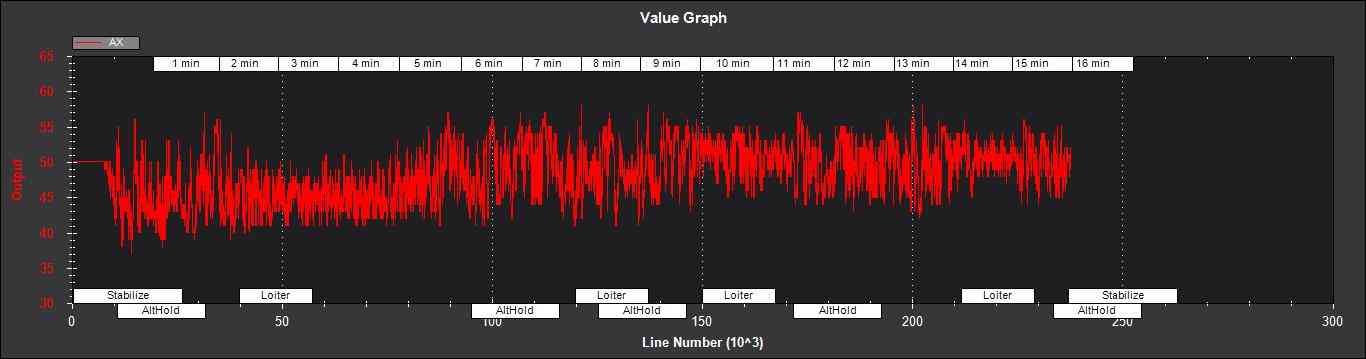
If it swings close to 100 or 0 % for parts of the flight, then this indicates that you likely have aliasing affecting your accelerometer data and you should look for solutions to reduce this (eg vibration isolation mounts for your autopilot).
AZ1bias - Z accelerometer bias for IMU1 (cm/s:sup:2)
AZ2bias - Z accelerometer bias for IMU2 (cm/s:sup:2)
VWN,VWE - North and East wind velocity (m/s). A positive value means the wind is moving in the direction of that axis, eg a positive North wind velocity is blowing from the South.
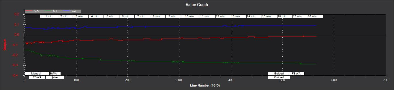
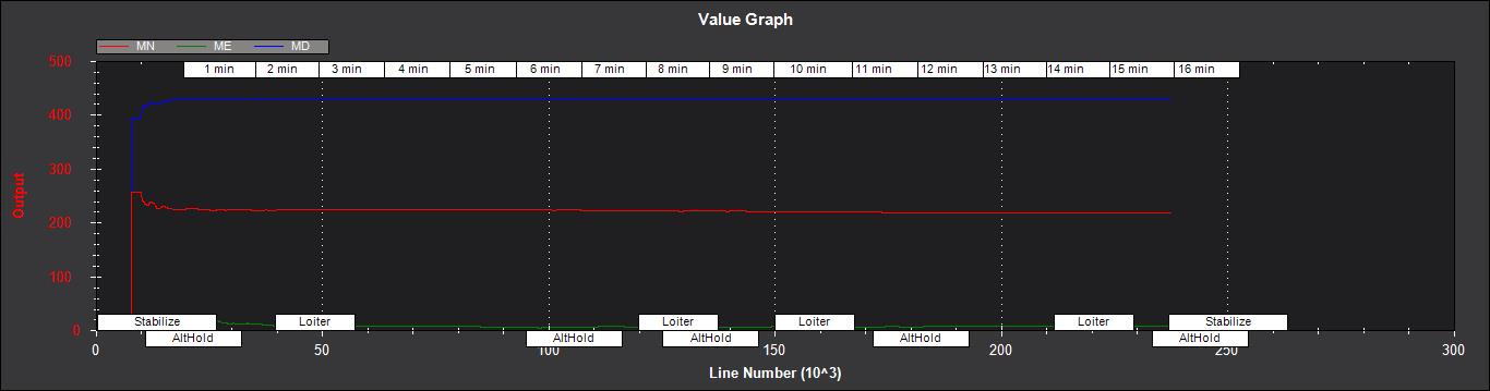
MN,ME,MD - North, East, Down earth magnetic field strength (sensor
units). If you are flying quickly, or are at low speed with
EKF_MAG_CAL enabled, these will slowly change during flight as the
filter ‘learns’ the earth’s magnetic field.
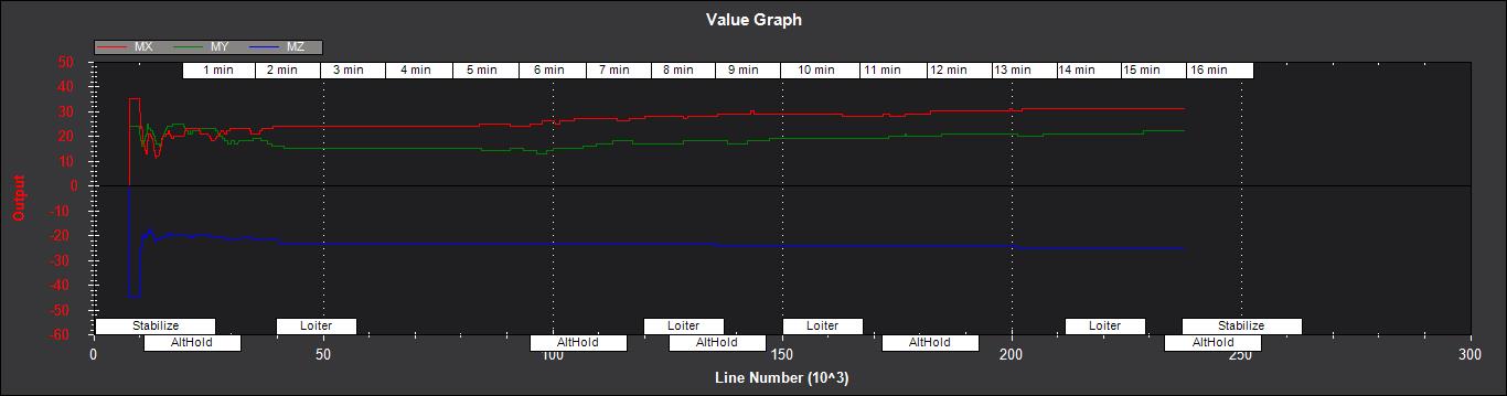
MX,MY,MZ - X, Y, Z body magnetic field biases (sensor units). If you
are flying quickly, or are at low speed with EKF_MAG_CAL enabled,
these will slowly change during flight as the filter ‘learns’ the
earth’s magnetic field. These have the same meaning as the compass
offsets, but are the opposite sign (eg in the following figure MX
stabilises at a value of +35, indicating that a COMPASS_OFS_X value
of -35 should be used.
EKF3
This message contains the innovations for each sensor (GPS, barometer, magnetometer and airspeed). Innovations are the difference between the value predicted using the IMU data before corrections are applied, and the value measured by the sensor.
TimeMS - Time in msec from startup
IVN,IVE,IVD - Innovations for the North,East,Down GPS velocity measurements (m/s). These are an important measure of health for the navigation filter. If you have god quality IMU and GPS data they will be small and around zero as shown in the following figure:
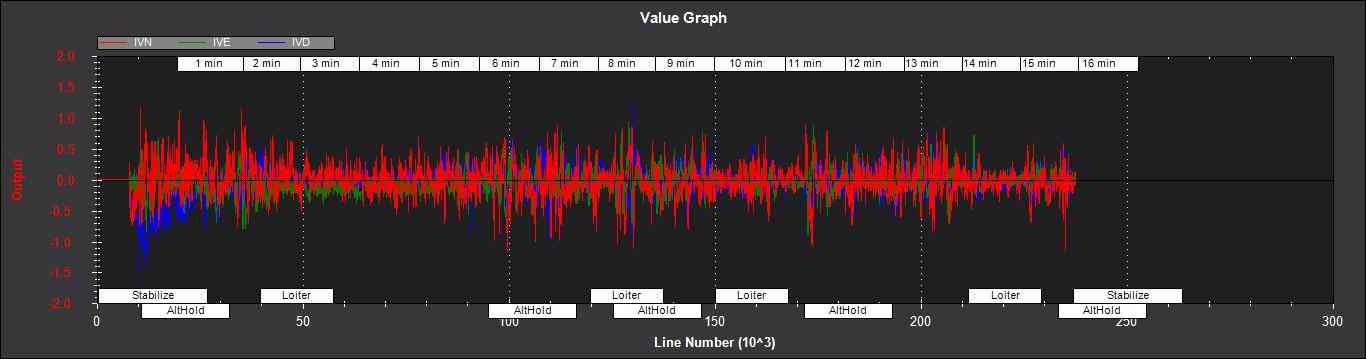
The noise level on these innovations when the vehicle is not maneuvering
can be used to set the value of EKF_VELNE_NOISE and
EKF_VELD_NOISE. For example in the above figure, the velocity noise
when the vehicle was non-manoeuvring was around +-0.3 m/s for both the
North,East and Down velocities. This means that a good starting value
for EKF_VELNE_NOISE and EKF_VELD_NOISE for this example would
be 0.3 m/s.
IPN,IPE - Innovations in the North, East GPS position measurements (m). Similarly to the velocity innovations, they should be small and centred on zero as in the following example:
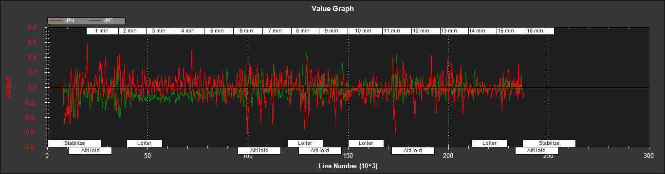
The noise levels on these innovations can be used to set the value of
EKF_POSNE_NOISE. In the above figure, the noise sits within a band
of +-0.5m, so a good starting value for the value of EKF_POSNE_NOISE
in this example would be 0.5m.
IPD - Innovations on the barometer height measurement (m). They should be small and centered on zero as in the following example, although transients of around 2m are common when sudden height changes or manoeuvres are performed due to IMU errors, sensor lag and the effect of changes in airflow on he barometer reading.
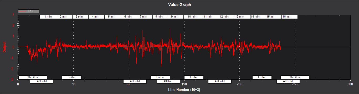
In the above figure it can be seen that there is a small 1m negative
offset that is removed after 2min. This is due to bias errors on the Z
accelerometers which take time to be learned by the filter and
compensated for. In this example, the underlying sensor noise is low at
about +-0.15m, which indicates a good starting value for
EKF_ALT_NOISE for plane applications would be 0.15m.
Note: For copter, experience has shown the value of
EKF_ALT_NOISE normally has to be increased above the theoretical
value to smooth out the height response
IMX,IMY,IMZ - Innovations for the Magnetometer X,Y,Z measurements. These should be centered around zero and not exceed +- 50 during manoeuvres as shown in the following figure:
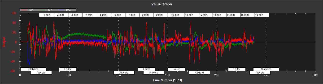
In the above example EKF_MAG_CAL was set to 1, so the copter quickly
learnt the magnetometer biases (compass offsets). Although the
underlying noise of the magnetometer is relatively low (5 or less in
most cases), there are other errors due to differences in scale factors
between axes, magnetometer misalignment, and varying magnetic fields
produced by electrical power systems that cause larger errors. Typically
these result in sharp transients of about 50 in the innovations, as can
be seen in the above figure. For this reason the default value of
EKF_MAG_NOISE is set to 0.05 (which represents a noise of 50 in
sensor units).
The following figure is taken from a slow speed copter flight with a bad
magnetometer calibration and EKF_MAG_CAL = 0. The innovations vary
noticeably as the vehicle changes its orientation.

IVT - Innovation for the true airspeed measurement (m/s). This will be zero if the airspeed sensor is not fitted or is not being used (e.g. on ground). It should be centered around zero if the airspeed sensor is calibrated correctly, but will vary in noise level depending on how gusty the flight conditions are. the following is an example from a flight with a well calibrated airspeed sensor in moderate wind conditions of around 7m/s in low turbulence:
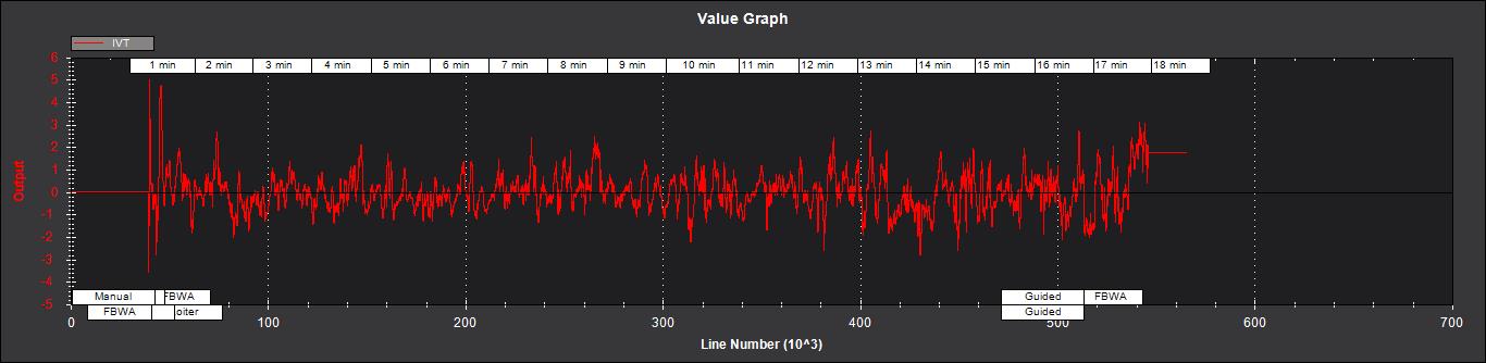
A constant offset of 1m/s from zero would indicate a steady 1m/s airspeed error. Steady airspeed errors can be caused if the airspeed sensor is uncovered during initialisation on a windy day resulting in a significant pressure offset, is out of cal, or has experienced a large change in temperature since initialisation.
This figure can also be used to set the value for EKF_EAS_NOISE. For
the example shown above, the total noise (including gusts) is around 1.4
m/s, so this would be a good starting value for EKF_EAS_NOISE.
EKF4
This message contains plots showing how each sensor is performing
relative to the error gates set by the EKF_POS_GATE,
EKF_VEL_GATE, EKF_HGT_GATE, EKF_MAG_GATE and
EKF_EAS_GATE. These parameters control how inconsistent a
measurement is allowed to be before the filter won’t use it. When we
refer to inconsistency of measurements in this section, we are talking
about the amount of difference between the measurement predicted by the
filter and the measurement taken by the sensor. Checking measurements
for inconsistencies is particularly important with GPS, because GPS
measurements can have very large transient position and velocity errors
that would cause a crash if they were to be used by the filter. The
following messages are available in EKF4:
TimeMS - Time in msec from startup
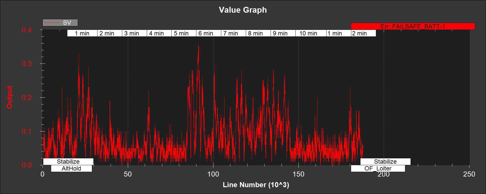
SV - ratio of the combined GPS velocity inconsistency to the limit
set by the EKF_VEL_GATE parameter. For a flight with good GPS data,
this can have the occasional spike to over 1/2, but should never go
above 1. If this line goes above 1, then it indicates that the filter
stopped using the GPS velocity data for that period in flight. This
should never happen with good sensor data. The following figure shows
SV taken from a quadrotor flight with 9 to 10 satellites in good GPS
conditions, using the default parameters. If this line is too high and
goes above 1 with good GPS, then the EKF_VEL_GATE parameter should
be increased.
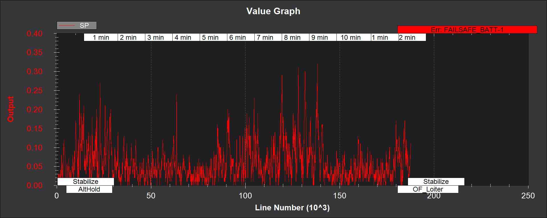
SP - ratio of the GPS total position inconsistency to the limit set
by the EKF_POS_GATE parameter. For a flight with good GPS data, this
can have the occasional spike to over 1/2, but should never go above 1.
If this line goes above 1, then it indicates that the filter stopped
using the GPS position data for that period in flight. This should never
happen with good sensor data. The following figure shows SP taken
from a quadrotor flight with 9 to 10 satellites in good GPS conditions,
using the default parameters. If this line is too high and goes above 1
with good GPS, then the EKF_POS_GATE parameter should be
increased.
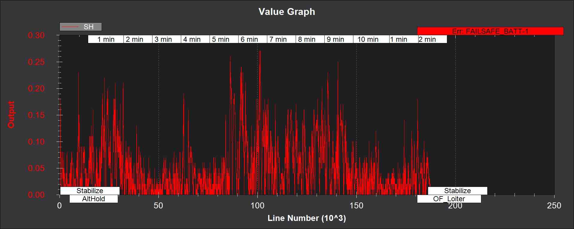
SH - ratio of the barometer height inconsistency to the limit set by
the EKF_HGT_GATE parameter. This can have the occasional spike to
over 1/2, but should never go above 1. If this line goes above 1, then
it indicates that the filter stopped using the barometer data for that
period in flight. This should never happen with good sensor data. The
following figure shows SH taken from a quadrotor flight at airspeeds
up to 16 m/s, using the default parameters. If this line is too high and
goes above 1, then the EKF_HGT_GATE parameter should be increased.
Factors that can cause this to be high include airflow past the
autopilot affecting the barometer reading and accelerometer errors due
to sensor drift or aliasing.
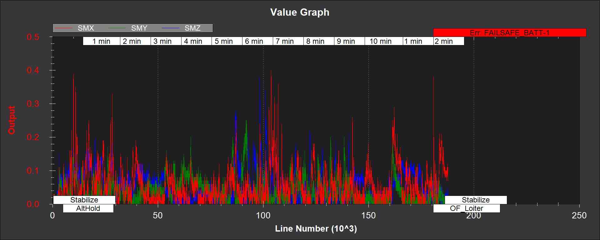
SMX,SMY,SMZ - ratio of the magnetometer X,Y and Z measurement
inconsistencies to the limit set by the EKF_MAG_GATE parameter. This
can have the occasional spike to over 1/2, but should never go above 1.
If this line goes above 1, then it indicates that the filter stopped
using that component of magnetometer data for that period in flight.
This should never happen with good sensor data. The following figure
shows the SMX, SMY and SMZ data taken from a quadrotor flight using the
default parameters. If this line is too high and goes above 1 on a
regular basis, then it indicates a problem with the compass calibration
or installation. It is recommended that the reasons for the compass
errors be investigated first before resorting to increasing
the EKF_MAG_GATE parameter.
The next figure shows SMX, SMY and SMZ taken from a rover log, with the throttle demand ThrOutR also plotted.
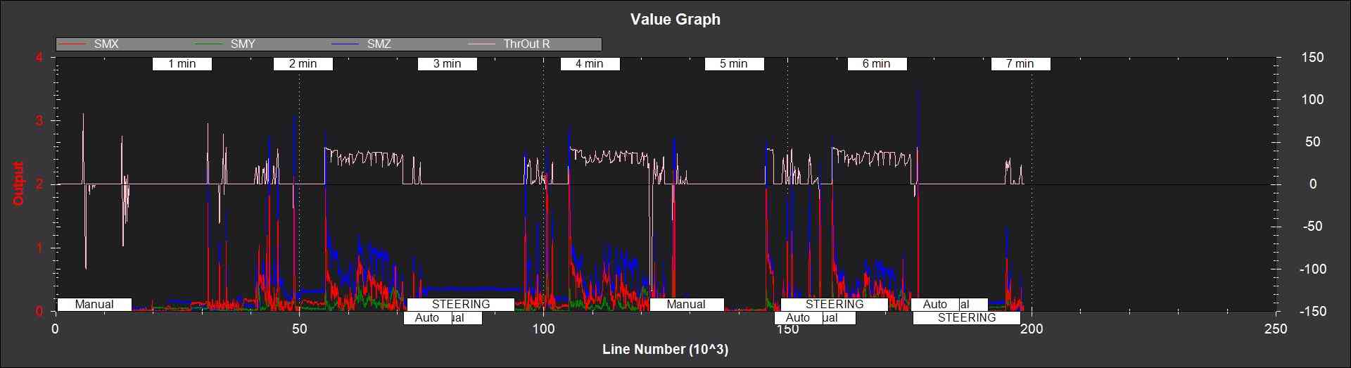
The large spikes above 1 every time the throttle steps up, and the large values during throttle operation can be clearly seen. In this example it would be recommended that steps be taken to reduce the amount of compass interference
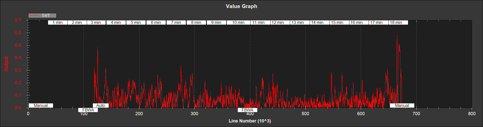
SVT - ratio of the airspeed measurement inconsistency to the limit
set by the EKF_EAS_GATE parameter. This can have the occasional
spike to over 1/2, but should rarely go above 1. If this line goes above
1, then it indicates that the filter stopped using the airspeed data for
that period in flight. Factors that can cause this to be high include
airspeed calibration errors, the presence of strong gusts and
turbulence, and rapid changes in wind speed. It is normal for this to be
higher at the start of the flight before the filter has estimated the
wind velocity.