The Cube Orange/+ With ADSB-In Overview
System Features
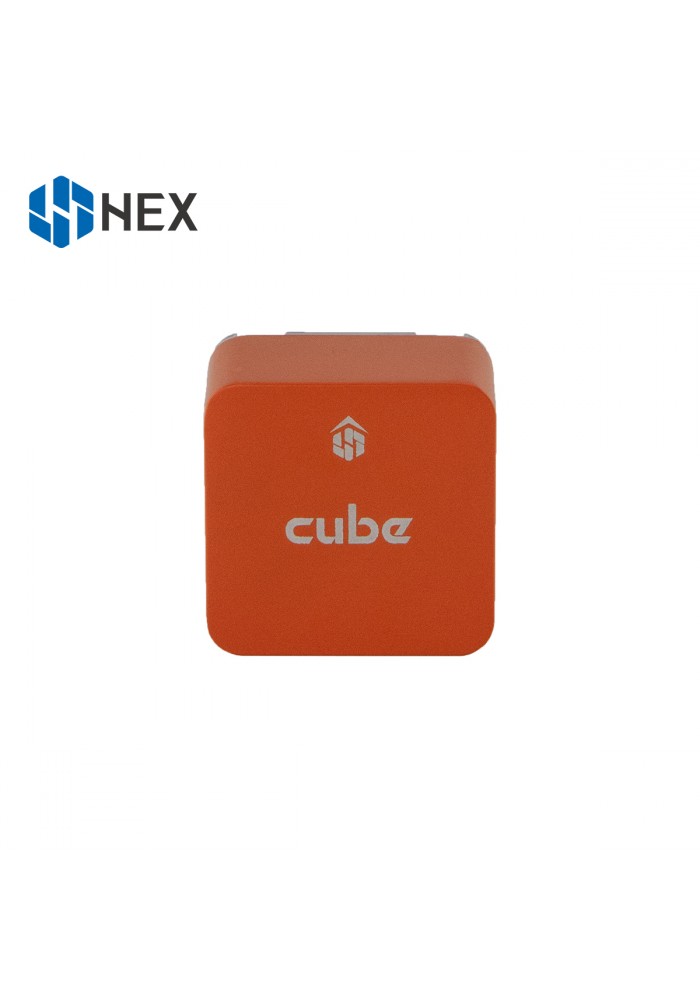
The Cube Orange autopilot is the latest and most powerful model in the CubePilot ecosystem. Designed for hobby users, commercial system integrators and UAS manufacturers the Cube Orange autopilot is part of a wide ecosystem of autopilot modules and carrier boards. All Cube models are compatible with all carriers which allows users to choose an off the shelf carrier board that best suits their needs. System designers are able to integrate the Cube directly into their designs via published carrier board specifications.
The Cube Orange is available as a standalone module or as a package with a new updated version of the original carrier board that now includes an integrated ADS-B In module from uAvionics.
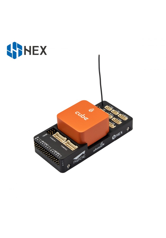
ADS-B Carrier Board
The new ADS-B carrier boards overall footprint is identical to the standard versions and the main changes compared to the original carrier are as follows:
Integration of uAvonix ADS-B IN Receiver on Serial 5
Built-In ADS-B Antenna
Removal of Intel Edison Bay and Debug USB Ports
All other specification and external connections remain identical to the original board as listed on the Cube Black page.
Cube Orange/+ Features
Faster H7 SOC with 1MB ram
Upgraded triple redundant IMU sensors for extra redundancy
2 sets of IMU are vibration-isolated mechanically, reducing the effect of frame vibration to state estimation
IMUs are temperature-controlled by onboard heating resistors, allowing optimum working temperature of IMUs
The entire flight management unit(FMU) and inertial management unit(IMU) are housed in a reatively small form factor (a cube).
Fully CubePilot carrierboard compatible, all inputs and outputs go through a 80-pin DF17 connector, allowing a plug-in solution for manufacturers of commercial systems. Manufacturers can design their own carrier boards to suit their specific needs now and in the future.
Specifications
Processor
32bit ARM® STM32H753 Cortex®-M7(with DP-FPU; Cube Orange+ uses ARM® STM32H757
400 Mhz/1 MB RAM/2 MB Flash
32 bit STM32F103 failsafe co-processor
Sensors
Three redundant IMUs (Accelerometers/Gyroscopes), Two Barometers, One Magnetometer
All sensors connected via SPI.
ICM 20649 integrated accelerometer / gyro, MS5611 barometer on base board
CubeOrange: - InvenSense ICM20602 IMU,ICM20948 IMU/MAG, MS5611 barometer on temperature controlled, vibration isolated board
CubeOrange+: - Invensense ICM42688 IMU, ICM20948 IMU/MAG, MS5611 barometer on temperature controlled, vibration isolated board
AK099916 MAG
Power
Redundant power supply with automatic failover
Servo rail high-power (7 V) and high-current ready
All peripheral outputs over-current protected, all inputs ESD protected
Interfaces
14x PWM servo outputs (8 from IO, 6 from FMU)
S.Bus servo output
R/C inputs for CPPM, Spektrum / DSM and S.Bus
Analogue / PWM RSSI input
5x general purpose serial ports, 2 with full flow control
2x I2C ports
SPI port (un-buffered, for short cables only not recommended for use)
2x CAN Bus interface
3x Analogue inputs (3.3V and 6.6V)
High-powered piezo buzzer driver (on expansion board)
High-power RGB LED (I2C driver compatible connected externally only)
Safety switch / LED
Optional carrier board for Intel Edison (now obsolete)
The Cube connector pin assignments
TELEM1, TELEM2 ports
| Pin | Signal | Volt |
|---|---|---|
| 1 (red) | VCC | +5V |
| 2 (blk) | TX (OUT) | +3.3V |
| 3 (blk) | RX (IN) | +3.3V |
| 4 (blk) | CTS | +3.3V |
| 5 (blk) | RTS | +3.3V |
| 6 (blk) | GND | GND |
GPS1 port
| Pin | Signal | Volt |
|---|---|---|
| 1 (red) | VCC | +5V |
| 2 (blk) | TX (OUT) | +3.3V |
| 3 (blk) | RX (IN) | +3.3V |
| 4 (blk) | SCL I2C2 | +3.3V |
| 5 (blk) | SDA I2C2 | +3.3V |
| 6 (blk) | Button | GND |
| 7 (blk) | button LED | GND |
| 8 (blk) | GND | GND |
GPS2 port
| Pin | Signal | Volt |
|---|---|---|
| 1 (red) | VCC | +5V |
| 2 (blk) | TX (OUT) | +3.3V |
| 3 (blk) | RX (IN) | +3.3V |
| 4 (blk) | SCL I2C1 | +3.3V |
| 5 (blk) | SDA I2C1 | +3.3V |
| 6 (blk) | GND | GND |
ADC
| Pin | Signal | Volt |
|---|---|---|
| 1 (red) | VCC | +5V |
| 2 (blk) | ADC IN | 6.6Vmax,pin 8 |
| 3 (blk) | GND | GND |
I2C2
| Pin | Signal | Volt |
|---|---|---|
| 1 (red) | VCC | +5V |
| 2 (blk) | SCL | +3.3 (pullups) |
| 3 (blk) | SDA | +3.3 (pullups) |
| 4 (blk) | GND | GND |
CAN1&2
| Pin | Signal | Volt |
|---|---|---|
| 1 (red) | VCC | +5V |
| 2 (blk) | CAN_H | +12V |
| 3 (blk) | CAN_L | +12V |
| 4 (blk) | GND | GND |
POWER1
| Pin | Signal | Volt |
|---|---|---|
| 1 (red) | VCC | +5V |
| 2 (red) | VCC | +5V |
| 3 (blk) | CURRENT | up to +3.3V,pin 15 |
| 4 (blk) | VOLTAGE | up to +3.3V,pin 14 | 5 (blk) | GND | GND | 6 (blk) | GND | GND |
POWER2
| Pin | Signal | Volt |
|---|---|---|
| 1 (red) | VCC | +5V |
| 2 (red) | VCC | +5V |
| 3 (blk) | CURRENT | up to +3.3V,pin 4 |
| 4 (blk) | VOLTAGE | up to +3.3V,pin 13 | 5 (blk) | GND | GND | 6 (blk) | GND | GND |
USB
| Pin | Signal | Volt |
|---|---|---|
| 1 (red) | VCC | +5V |
| 2 (blk) | D_plus | +3.3V |
| 3 (blk) | D_minus | +3.3V |
| 4 (blk) | GND | GND |
| 5 (blk) | BUZZER | battery voltage |
| 6 (blk) | Boot/Error LED |
RSSI Input
Analog/PWM RSSI Input is pin 103
CubePilot Ecosystem
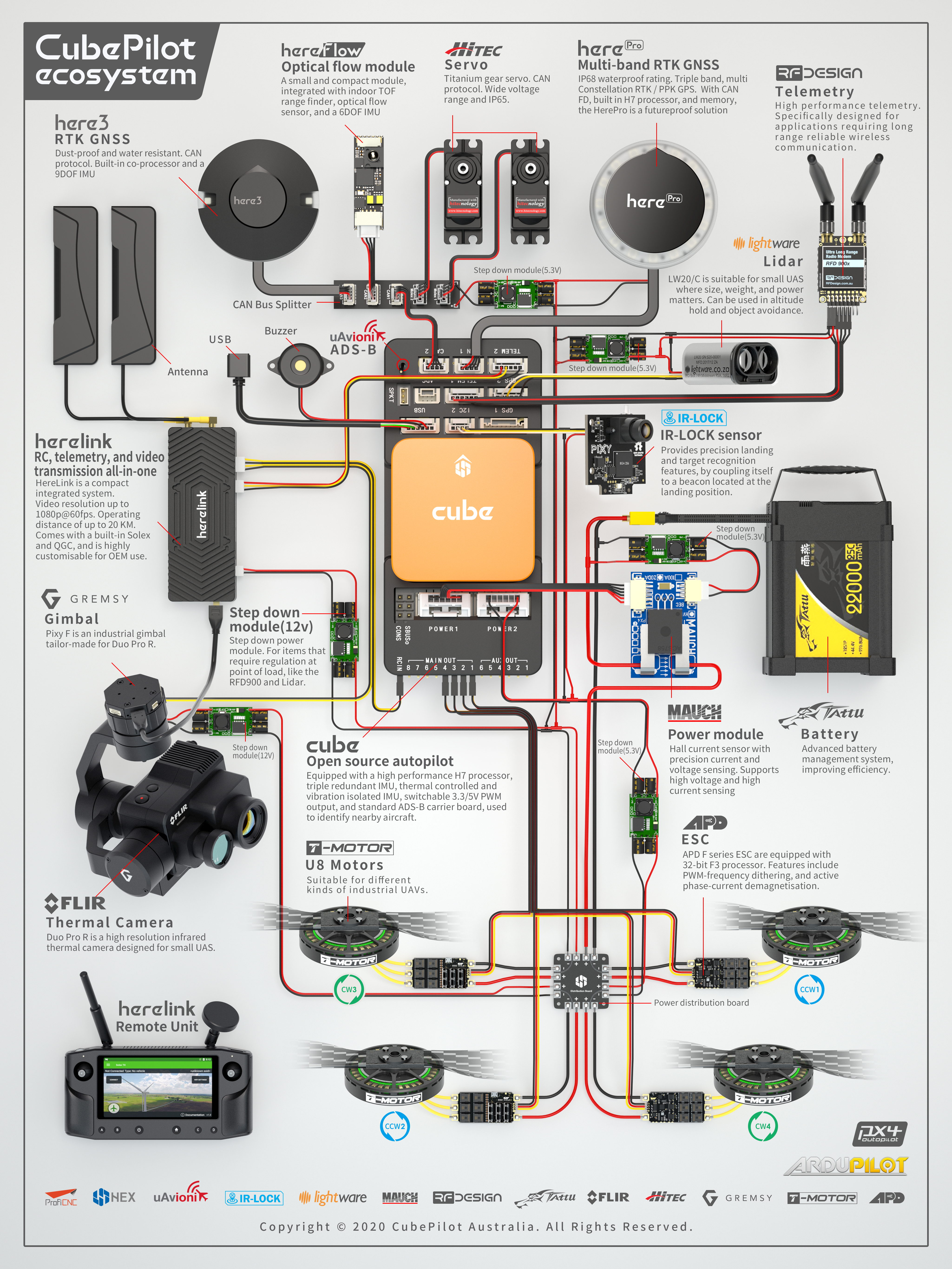
More Information
For more information and instructions on setting up and using the CubePilot system see CubePilot Docs
For technical help and support on the CubePilot system see CubePilot Forum
Company information on CubePilot can be found at www.cubepilot.com
Carrier Board Design
The reference design files of the standard carrier board are available in github, or here ,this serves as a starting point for designers to design their own system based on The Cube autopilot.
Where to Buy
Official retailers are listed here.
More Images