QioTek Zealot H743
Note
This autopilot is supported in 4.2 and later firmware
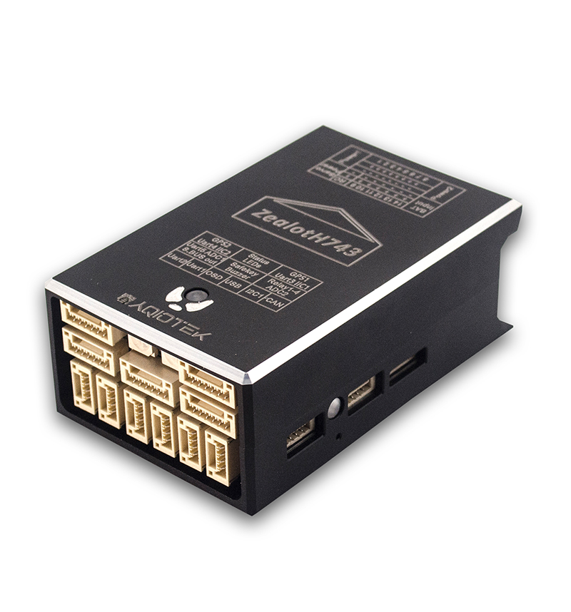
The QioTek Zealot H743 is an internally vibration dampened autopilot with a protective CNC metal case for ruggedness. It features fully redundant sensors, expanded number of outputs, temperature controlled IMUs, and is the first high performance autopilot with integrated OSD chip.
Specifications
Processor:
MCU - STM32H743VIT6
16KB FRAM - FM25V01
AT7456E OSD
Sensors
Gyro/Accelerometers: - Standard: ICM42688P, ICM20689, ICM40605 - Industrial: IIM42652, ICM42688P, ICM20689 - Insdustry Application Version: ADIS16170, IIM42652, ICM42688P
Barometers: 2x DSP310
Compass: QMC5883L
Power
4.1-6.0VDC from USB (internal circuitry and RX only) or via 2 x PowerModule connectors, or via internal BEC off VBAT input pin. All 5V pins are powered when USB, or Power Module(s), or VBAT input is used.
Internal 5V, 1.5A BEC directly can be used with up to 6S LIPO batteries to supply board and peripheral power up to 1.5A max with voltage only monitoring via BATT2 monitor (500ma max recommended).
ADC monitoring of board voltage
ADC monitoring of Servo/Output’s power rail
Interfaces/Connectivity
14 PWM Outputs with independent power rail for external power source
4 Relay outputs
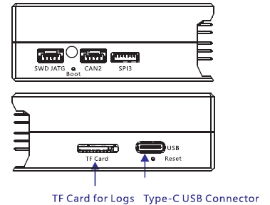
MicroSD card reader
Micro USB or remote USB via a JST_GH connector
Builtin RGB LED
Camera Input and Video Output
External Buzzer interface
2, 6.6V tolerant ADC inputs for RSSI, Analog Airspeed, etc.
5 UARTs
2, DroneCAN/CAN interfaces
Safety Switch connector
Dimensions
Weight 65g
Size 42mm x 65mm x 25mm
Connector pin assignments
Unless noted otherwise all connectors are JST GH
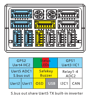
UART1(TELEM1), UART2(TELEM2) ports
| Pin | Signal | Volt |
|---|---|---|
| 1 | VCC | +5V |
| 2 | TX (OUT) | +3.3V |
| 3 | RX (IN) | +3.3V |
| 4 | GND | GND |
OSD
| Pin | Signal | Volt |
|---|---|---|
| 1 | VIN | +3.3V |
| 2 | GND | GND |
| 3 | GND | GND |
| 4 | VOUT | 3.3V |
USB remote port
| PIN | SIGNAL | VOLT |
|---|---|---|
| 1 | USB VDD | +5V |
| 2 | DM | +3.3V |
| 3 | DP | +3.3V |
| 4 | GND | GND |
I2C1 port
| PIN | SIGNAL | VOLT |
|---|---|---|
| 1 | VCC | +5V |
| 2 | SCL1 | +3.3V |
| 3 | SDA1 | +3.3V |
| 4 | GND | GND |
DroneCAN/CAN ports
| PIN | SIGNAL | VOLT |
|---|---|---|
| 1 | VCC | +5V |
| 2 | CAN_H | +12V |
| 3 | CAN_L | +12V |
| 4 | GND | GND |
USART5/ADC1/SBus Out port
| PIN | SIGNAL | VOLT |
|---|---|---|
| 1 | VCC | +5V |
| 2 | TX5 | +3.3V |
| 3 | RX5 | +3.3V |
| 4 | SBUS Out | +3.3V |
| 5 | ADC1 | +6V |
| 6 | GND | GND |
Safety/Buzzer port
| PIN | SIGNAL | VOLT |
|---|---|---|
| 1 | VCC3.3 | +3.3V |
| 2 | VCC5.5 | +5V |
| 3 | SafKey | +3.3V |
| 4 | SafLED | +3.3V |
| 5 | BUZZER- | +5V |
| 6 | GND | GND |
Relay/ADC2 port
| PIN | SIGNAL | VOLT |
|---|---|---|
| 1 | ADC2 | +6V |
| 2 | Relay1 | +5V |
| 3 | Relay2 | +5V |
| 4 | Relay3 | +5V |
| 5 | Relay4 | +5V |
| 6 | GND | GND |
USART3(GPS1/I2C1), UART4(GPS2/I2C2) ports
| PIN | SIGNAL | VOLT |
|---|---|---|
| 1 | VCC | +5V |
| 2 | TX | +3.3V |
| 3 | RX | +3.3V |
| 4 | SCL | +3.3V |
| 5 | SDA | +3.3V |
| 6 | GND | GND |
Power1, Power2 ports
| PIN | SIGNAL | VOLT |
|---|---|---|
| 1 | VCC | +5V |
| 2 | VCC | +5V |
| 3 | CURRENT | +3.3V |
| 4 | VOLTAGE | +3.3V |
| 5 | GND | GND |
| 6 | GND | GND |
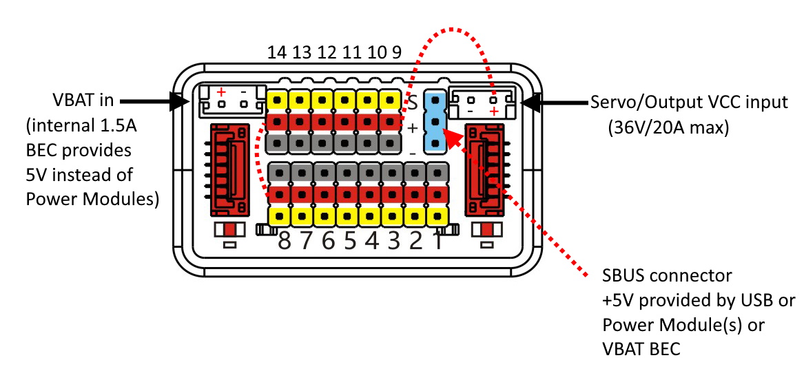
VBAT Input
30V maximum input. A 5V, 1.5A regulator drops this input to the +5V used and supplied by the autopilot. Do not connect power to this input if Power Module 2 input is used as they share the BATT2 voltage monitoring circuitry. This connector is a JST-EH type.
SERVO VCC Rail Input
This provides a means to power servos attached to the output connector block by an external BEC or power source. Maximum power rating is 36V @ 20A.
RC Input
All compatible RC protocols can be decoded by attaching the Receiver’s output to the SBUS input pin next to the Servo/Output VCC input connector. Note that some protocols such as CRSF or FPort including telemetry, require connection to, and setup of, one of the UARTs instead of this pin.
Default UART order
SERIAL0 = console = USB
SERIAL1 = Telemetry1 = USART1
SERIAL2 = Telemetry2 = USART2
SERIAL3 = GPS1 = USART3
SERIAL4 = GPS2 = UART4
SERIAL5 = USER = UART5
Dshot capability
All motor/servo outputs are Dshot and PWM capable. However, mixing Dshot and normal PWM operation for outputs is restricted into groups, ie. enabling Dshot for an output in a group requires that ALL outputs in that group be configured and used as Dshot, rather than PWM outputs. The output groups that must be the same (PWM rate or Dshot, when configured as a normal servo/motor output) are: 1/2, 3/4/13/14, 5/6/7/8, 9/10/11/12. Outputs 13 and 14 cannot support Dshot, only PWM, so if 3 and four are set to DShot, 13 and 14 cannot be used.
Note
For BShot capability on outputs 9-14, use the firmware in the “QioTekZealotH743-bdshot” folder on the Firmware Server
Battery Monitor Settings
These should already be set by default. However, if lost or changed:
Enable Battery monitor with these parameter settings :
BATT_MONITOR =4
Then reboot.
DroneCAN capability
There are 2 CAN ports which allow connecting two independent CAN bus outputs. Each of these can have multiple CAN peripheral devices connected. A CAN splitter board is included with the autopilot. Please refer to CAN Bus Setup for information on how to configure CAN on the board.