FlywooF405 Pro
Specifications
Processor and Sensors
STM32F405 ARM microcontroller
ICM42688 IMU (Gyro and Accelerometers)
BMP280 Barometer
AT7456E OSD
16Mbytes logging flash
Interfaces
9x PWM outputs (PWM9 for Neopixel LED)
1x RC input (PWM/PPM, SBUS)
6x serial port inputs (including RC input listed above)
1x I2C for external compass or airspeed sensor
4 in 1 ESC connector
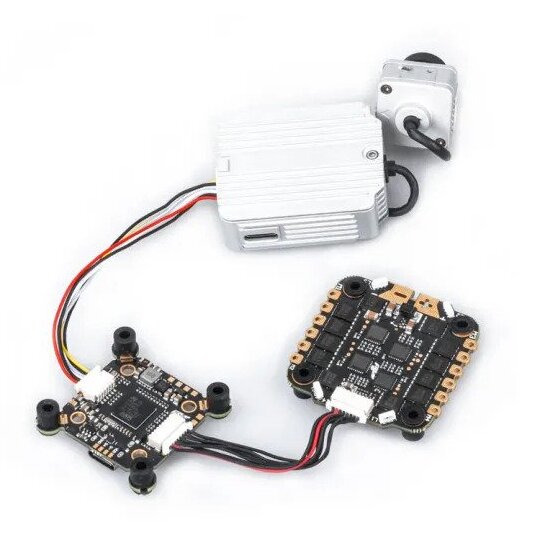
DJI Air Unit connector
USB-C connector
Power
9V ~ 25V DC input power (3S-6S)
5V 2A BEC for peripheral
10V 2A for Video
Size and Dimensions
20mm x 20mm or 30.5mm x 30.5mm mount pattern
5.5g
Where to Buy
Available from various retailers and directly from the manufacturer Flywoo
Pinouts
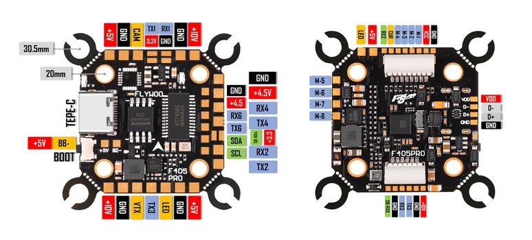
UART Defaults
The UARTs are marked Rn and Tn in the above pinouts. The Rn pin is the receive pin for UARTn. The Tn pin is the transmit pin for UARTn.
SERIAL0 -> USB
SERIAL1 -> USART1 (GPS)
SERIAL2 -> USART2 (RX only,ESC Telemetry)
SERIAL3 -> USART3 (DJI, DMA Enabled)
SERIAL4 -> UART4 (SBUS pin is inverted and connects to RX pin)(TX DMA Enabled) For normal UART use, BRD_ALT_CONFIG = 1.
SERIAL5 -> UART5 (RX5 is fed from an inverter connected to DJI connector’s SBUS pin, no TX pin)
SERIAL6 -> UART6 (RC serial input, DMA-enabled)
RC Input
RC input is configured on the SBUS pin which is inverted and feeds the R4 (UART4_RX) pin for most RC unidirectional protocols, including PPM.
For CRSF/ELRS/SRXL2 connection of those to UART6 is pre-configured.
The DJI connector’ SBUS input can be used for SBUS only, but SERIAL5_PROTOCOL must be set to “23” and SERIAL6_PROTOCOL must be changed to something other than “23”.
Dshot capability
The FlywooF405 Pro supports up to 9 PWM outputs. The M1 to M4 outputs are on the esc connector and are bi-directional DShot capable, M5 to M8 on solder pads and DShot capable, plus LED pad(PWM output 9) for LED strip or another PWM output.
The PWM is in 3 groups:
PWM 1-2,5,7 in group1
PWM 3-4 in group2
PWM 6,8 in group2
PWM 9 in group3
Channels within the same group need to use the same output protocol. If any channel in a group uses DShot then all channels in the group need to use DShot. Channels 1-4 also support bi-directional DShot.
GPIOs
The FlywooF405 Pro outputs can be used as GPIOs (relays, buttons, RPM etc). To use them you need to set the output’s SERVOx_FUNCTION to -1. See GPIOs page for more information.
The numbering of the GPIOs for PIN variables in ArduPilot is:
PWM1 50
PWM2 51
PWM3 52
PWM4 53
PWM5 54
PWM6 55
PWM7 56
PWM8 57
PWM9 58
RSSI/Analog Airspeed Input
An analog input is provided and its reference pin number is “10”
OSD Support
The FlywooF405 Pro has an on-board OSD using OSD_TYPE = 1 (MAX7456 driver). The CAM and VTX pins provide connections for using the internal OSD.
DJI Video and OSD
A JST-GH-6P connector supports a standard DJI HD VTX connection and SERIAL3 is already setup for this by default. Pin 1 of the connector is 10v so be careful not to connect this to any peripheral requiring 5v.
Battery Monitoring
The board has a internal voltage sensor and connections on the ESC connector for an external current sensor input. The voltage sensor can handle up to 6S LiPo batteries.
The default battery parameters are:
BATT_MONITOR = 4
BATT_VOLT_PIN = 13
BATT_CURR_PIN = 12
BATT_VOLT_MULT = 11.0
BATT_AMP_PERVLT = 58.8 (will need to be adjusted for whichever current sensor is attached)
Compass
The FlywooF405 Pro does not have a builtin compass, but you can attach an external compass using I2C on the SDA and SCL pads.
Firmware
This board does not come with ArduPilot firmware pre-installed. Use instructions here to load ArduPilot the first time Loading Firmware onto boards without existing ArduPilot firmware.
Firmware for this board can be found here in sub-folders labeled “FlywooF405Pro”. Firmware is provided only for Copter/Heli but may be built for other vehicles using the ArduPilot Custom Firmware Build Server