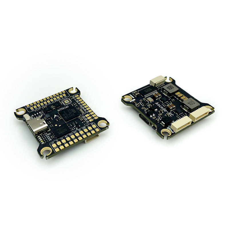
Aocoda-RC H743Dual

the above image and some content courtesy of aocoda-rc.com
Note
Both versions use the same firmware and differ in the IMU used
Specifications
Processor
STM32H743VIH6 (480MHz)
128MByte Flash for datalogging
Sensors
InvenSense MPU6000 or 2x BOSCH BMI270 IMU (accel, gyro)
DPS310 barometer
Voltage & 130A current sensor
Power
3-6S Lipo input power
5V 2.5A BEC for peripherals
9V 3A BEC for video
Interfaces
USB port (type-C)
7x UARTS
12x PWM outputs via two 8 pin ESC connectors and/or solder pads
1x RC input PWM/SBUS
I2C port for external compass, airspeed sensor, etc.
DJI Goggles
2x Power Monitor
Buzzer and LED stripe
Built-in OSD
Size and Dimensions
37 mm x 37 mm
8.8 g
Mounting Hole
30.5 mm x 30.5 mm
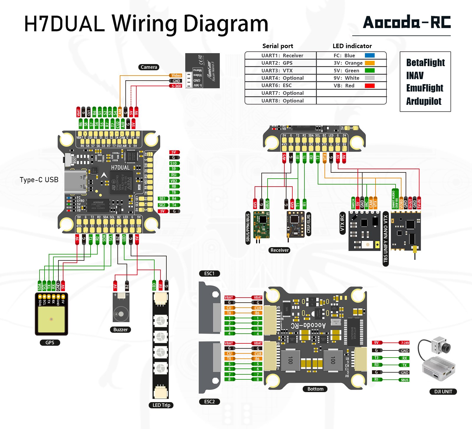
Wiring Diagram

Default UART order
SERIAL0 = USB (MAVLink2)
SERIAL1 = UART1 (RCinput)
SERIAL2 = UART2 (GPS)
SERIAL3 = UART3 (VTX or DJI HD Air Unit)
SERIAL4 = UART4 (USER)
SERIAL5 = not available
SERIAL6 = UART6 (ESC Telemetry)
SERIAL7 = UART7 (USER)
SERIAL8 = UART8 (USER)
Note
Serial port protocols (Telem, GPS, etc.) can be adjusted to personal preferences.
RC Input
RC input is configured by default on SERIAL1 (USART1). PPM receivers are not supported. The 4V5 pin is supplied by both USB and on board 5V BEC from battery.
PPM is not supported.
SBUS/DSM/SRXL connects to the RX1 pin.
FPort requires connection to TX1. Set SERIAL1_OPTIONS = 7. See FPort Receivers.
CRSF also requires a TX1 connection, in addition to RX1, and automatically provides telemetry.
SRXL2 requires a connection to TX1 and automatically provides telemetry. Set SERIAL6_OPTIONS to “4”.
Any UART can be used for RC system connections in ArduPilot also. See Radio Control Systems for details.
RSSI/Analog Airspeed Input
Analog inputs are provided.
Airspeed reference pin number is “4”
RSSI reference pin number is “8”.
Note
set RSSI_TYPE = 1 for analog RSSI, = 3 for RSSI provided by RC protocols such as CRSF.
OSD Support
The Aocoda-RC H743Dual has an on-board OSD using OSD_TYPE = 1 (MAX7456 driver). The CAM and VTX pins provide connections for using the internal OSD.
DJI Video and OSD
An “SH1.0 6P” connector supports a standard DJI HD VTX connection and SERIAL3 is already setup for this by default. Pin 1 of the connector is 9V so be careful not to connect this to any peripheral requiring 5V.
Dshot capability
All motor/servo outputs 1-10 are Dshot, Bi-Directional DShot, and PWM capable. However, mixing Dshot and normal PWM operation for outputs is restricted into groups, ie. enabling Dshot for an output in a group requires that ALL outputs in that group be configured and used as Dshot, rather than PWM outputs.
The output groups that must be the same (PWM rate or Dshot, when configured as a normal servo/motor output) are: 1/2, 3/4, 5/6/9/10, 7/8. Outputs 11/12 (SE1/SE2) and 13 (LED) are in separate groups and are not Dshot capable.
GPIOs
The Aocoda-RC H743Dual outputs can be used as GPIOs (relays, buttons, RPM etc). To use them you need to set the output’s SERVOx_FUNCTION to -1. See GPIOs page for more information.
The numbering of the GPIOs for PIN variables in ArduPilot is:
PWM1 50
PWM2 51
PWM3 52
PWM4 53
PWM5 57
PWM6 56
PWM7 55
PWM8 54
PWM9 58
PWM10 59
PWM11 60
PWM12 61
LED 62
BUZZER 80
PINIO1 81 (internal)
VTX Power Control
GPIO 81 controls the VTX BEC output to pins marked “9V”. Setting this GPIO low removes voltage supply to pins.
Set a RELAYx_PIN to “81” to control the switching. Then select an RC channel for control (Chx) and set its RCx_OPTION to the appropriate Relay (1-6) that you had set its pin parameter above.
For example, use Channel 10 to control the switch using Relay 2:
RELAY2_PIN = “81”
RC10_OPTION = “34” (Relay2 Control)
Warning
PINIO1 is for 9V DC-DC control (HIGH:on; LOW:off). Default 9V DC is ON. Please install an antenna on VTX when battery powered.
Connecting a GPS/Compass module
This board does not include a GPS or compass so an external GPS/compass should be connected in order for autonomous modes to function.
Note
If the GPS is attached to UART2 TX/RX and powered from the adjacent 5V pins, a battery must be plugged in for power to be provided.
Tip
you could use the 4V5 pin to supply both the RC and the GPS without a battery attached on the bench for setup as long as the total current does not exceed the USB source (normally 1A on most computers)
Battery Monitor Settings
These should already be set by default. However, if lost or changed:
Enable Battery monitor with these parameter settings :
BATT_MONITOR = 4
Then reboot.
First group of battery monitor pins & options:
BATT_VOLT_PIN = 10
BATT_CURR_PIN = 11
BATT_VOLT_MULT = 11
BATT_AMP_PERVLT = 17.0 (note: Please calibrate before use, depending on current sensor.)
Second group of battery monitor pins & options:
BATT2_VOLT_PIN = 18
BATT2_CURR_PIN = 7
BATT2_VOLT_MULT = 11
BATT2_AMP_PERVLT = 17.0 (note: Please calibrate before use, depending on current sensor.)
Note
this autopilot uses a high precision current sensor input which is sensitive to ESC switching noise. Please check carefully before use that current readings are accurate across the usage range. If not, low ESR capacitors on the ESC power inputs may need to be added.
Where to Buy
Firmware
This board does not come with ArduPilot firmware pre-installed. Use instructions here to load ArduPilot the first time.
Firmware for these boards can be found here in sub-folders labeled “Aocoda-RC-H743Dual”.
Note
If you experience issues with the device ceasing to initialize after power up, see When Problems Arise section for H7 based autopilots for a possible solution.