Radio Control Calibration
This article shows how to perform radio control calibration using Mission Planner
Overview
RC transmitters allow the pilot to set the flight mode, control the vehicle’s movement and orientation and also turn on/off auxiliary functions (i.e. raising and lowering landing gear, etc).
RC Calibration involves capturing each RC input channel’s minimum, maximum and “trim” values so that ArduPilot can correctly interpret the input.
Check the Transmitter’s Setup
Ensure the battery is disconnected (this is important because it is possible to accidentally arm the vehicle during the RC calibration process)
Ensure the RC receiver is connected to the autopilot
Turn on your RC transmitter and if it has “trim tabs” ensure they are in the middle
Connect the autopilot to the PC using a USB cable
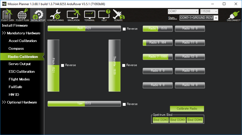
On the Mission Planner press the “Connect” button and open Mission Planner’s INITIAL SETUP | Mandatory Hardware | Radio Calibration screen
Some green bars should appear showing the ArduPilot is receiving input from the Transmitter/Receiver. If no bars appear check the receiver’s LED:
No lights may indicate that it is incorrectly wired to the autopilot. Look for connectors that may have been inserted upside down
A Red or flashing LED may indicate that your RC transmitter/receiver need be bound. See the manual that came with your RC equipment for instructions
Check the channel mapping in the transmitter (ie. check which inputs channels are controlled by the transmitter’s sticks, switches and knobs) by moving the sticks, knobs and switches and observing which (if any) green bars move. If this is the first time the transmitter is being used with ArduPilot it is likely that the transmitter’s channel mapping will need to be changed and normally this is done on the transmitter itself using its built-in configuration menu
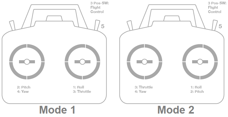
Determine if your transmitter is Mode1 or Mode2 (see below)
Roll stick should control channel 1
Pitch stick should control channel 2
Throttle stick should control channel 3
Yaw stick should control channel 4
A 3 or 6 position switch (to control the flight mode) should be setup to control Channel 5 (default,if using Copter) or Channel 8 (default, if using Rover or Plane). This channel can be moved by setting the FLTMODE_CH parameter in Plane or Copter, or MODE_CH in Rover.
On Copter, a tuning knob should control Channel 6
On Copter and Rover, any remaining two or three position switches can be setup to control auxiliary functions by mapping them to channels 7 to 12
Note that for reversing motor controls on Plane and Rover, the throttle range is range is normally divided into two parts: - Reverse throttle control: From
RCx_TRIM(typically 1500us) toRCx_MIN, where x is usually “3” for normal RC throttle input channel. This corresponds to motor outputs fromSERVOx_TRIMtoSERVOx_MIN, where “x” is the output controlling the motor, and assumes theSERVOx_REVERSEbit is not set. - Forward throttle control: FromRCx_TRIM(typically 1500us) toRCx_MAX, where x is usually “3” for normal RC throttle input channel. This corresponds to motor outputs fromSERVOx_TRIMtoSERVOx_MAX`, where "x" is the output controlling the motor, and assumes the ``SERVOx_REVERSEbit is not set. Using a spring-loaded stick may be most convenient, as it naturally returns to the neutral (stopped) position atRCx_TRIM.Note
For Plane, it is possible to use an AUX RC switch to provide easie reverse thrust control using the entire throttle stick range on non-sprung throttle sticks. Also, many set up a switch controlled mix in their RC transmitter to map throttle low stick position to output
RCx_TRIMafter calibration and either output RC as the stick is raised for reverse or forward operation depending on the TX switch position, giving full throttle stick range to forward or reverse operation.Move the transmitter’s roll, pitch, throttle, and yaw sticks and ensure the green bars move in the correct direction:
For roll, throttle and yaw channels, the green bars should move in the same direction as the transmitter’s physical sticks.
For pitch, the green bar should move in the opposite direction to the transmitter’s physical stick. This is not the default for many transmitters.
If one of the green bars moves in the incorrect direction, reverse the channel in the transmitter itself so that logging and outputs etc. are consistent. You may instead reverse the channel in ArduPilot by checking the “Reversed” checkbox (if shown), or directly changing the
RCx_REVERSEDparameter (where “x” is the input channel from 1 to 4).
Calibration
Open Mission Planner’s INITIAL SETUP | Mandatory Hardware | Radio Calibration screen
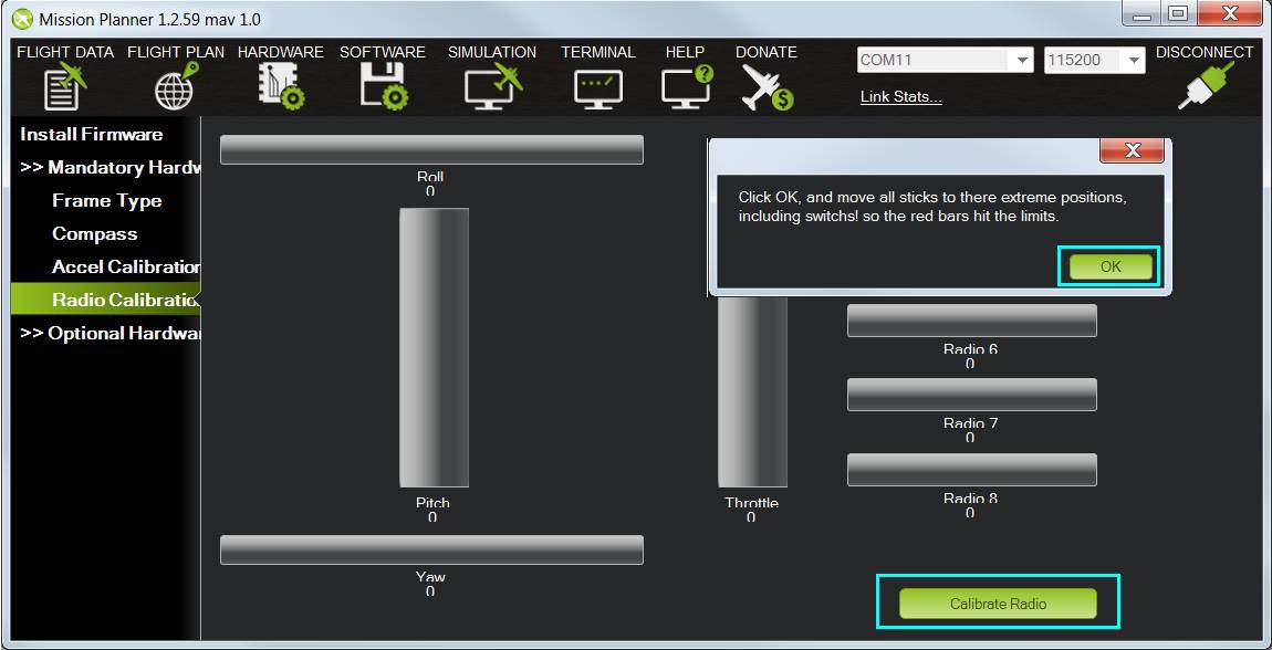
Click on the green “Calibrate Radio” button on the bottom right
Press “OK” when prompted to check the radio control equipment is on, battery is not connected, and propellers are not attached
Move the transmitter’s control sticks, knobs and switches to their limits. Red lines will appear across the calibration bars to show minimum and maximum values seen so far
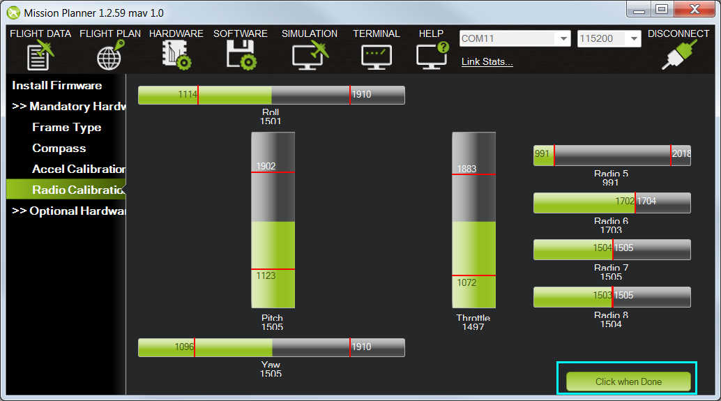
Select Click when Done
A window will appear with the prompt, “Ensure all your sticks are centered and throttle is down and click ok to continue”. Move the throttle to zero and press “OK”.
Mission Planner will show a summary of the calibration data. Normal values are around 1100 for minimums and 1900 for maximums.

If when testing your throttle stick you notice that the motor turns in a single direction, check in the full parameters list that
RCx_TRIMfor the throttle channel is set to the motor controller’s neutral value (usually about 1500 us). This should be detected and set automatically during calibration if you followed the procedure without forgetting to center your throttle in the last calibration step instead of the normal low position.
Mode1 and Mode2 Transmitters
There are two main transmitter configurations:
Mode 1: left stick controls pitch and yaw, the right stick will control throttle and roll.
Mode 2: left stick controls throttle and yaw; the right stick will control pitch and roll.
There are two alternative configurations:
Mode 3: left stick controls pitch and roll, the right stick will control throttle and yaw.
Mode 4: left stick controls throttle and roll; the right stick will control pitch and yaw.
Mode 3 is the opposite of Mode 2 and Mode 4 is the opposite of Mode 1, giving complete right handed/left handed user options.
Channel mappings
Plane default channel mappings are:
Channel 1: Roll
Channel 2: Pitch
Channel 3: Throttle
Channel 4: Yaw
Channel 8 (default): Flight modes. Mode selection can be mapped to any RC channel using the FLTMODE_CH parameter
Unused channels can be mapped to control additional peripherals.
Further Reading
Roll, pitch, throttle and yaw channel mappings can be changed using RCMAP Input Channel Mapping
Flight mode switch setup to specify which vehicle modes are enabled by each switch position can be found on the RC Transmitter Flight Mode Configuration page