SpeedyBeeF405-Mini
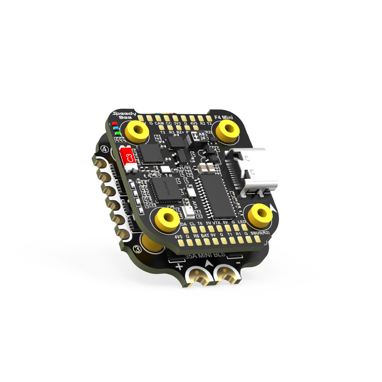
the above image and some content courtesy of SpeedyBee and the autopilot is shown with a companion 4in1 ESC as a stack.
Note
Due to flash memory limitations, this board does not include all ArduPilot features. See Firmware Limitations for details.
Specifications
Processor
STM32F405RGT6 ARM (168MHz)
AT7456E OSD
8MByte flash for logging
Sensors
ICM-42688P IMU (accel, gyro)
DSP-310 barometer
Voltage Sensor, Input for external current sensor
Power
4.75-5.25V input
9V 3A BEC for powering Video Transmitter
5V, 2A BEC for internal and peripherals
Interfaces
4x PWM outputs DShot capable (Serial LED output is 5th output)
1x RC input
5x UARTs/serial for GPS and other peripherals, 6th UART internally tied to Wireless board)
I2C port for external compass, airspeed, etc.
USB-C port
Size and Dimensions
30mm x 32mm x 7.8mm
9.6g
Where to Buy
User Manual
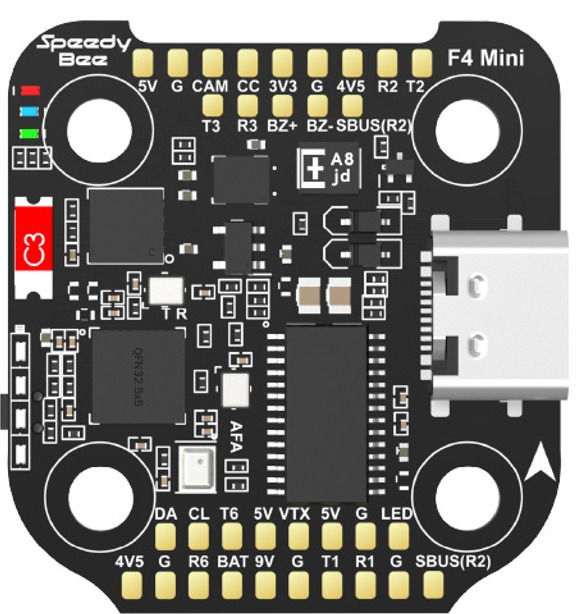
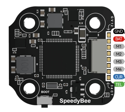
Pinout
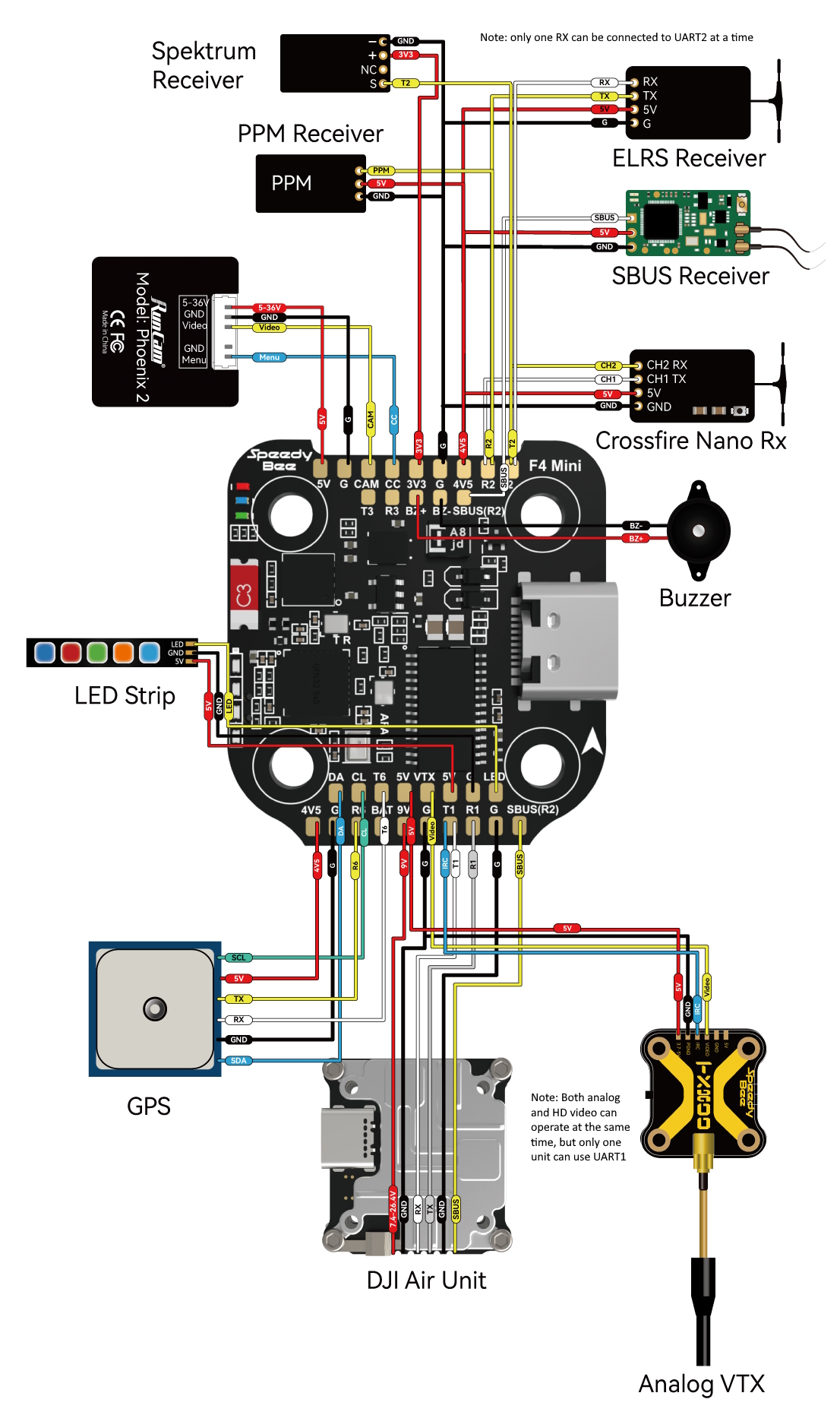
Wiring Diagram
Default UART order
The UARTs are marked Rn and Tn in the above pinouts. The Rn pin is the receive pin for UARTn. The Tn pin is the transmit pin for UARTn.
SERIAL0 -> USB
SERIAL1 -> UART1 (DJI-VTX, DMA-enabled)
SERIAL2 -> UART2 (RX, DMA-enabled)
SERIAL3 -> UART3
SERIAL4 -> UART4 (connected to internal BT module, not currently usable by ArduPilot)
SERIAL5 -> UART5 (ESC Telemetry, RX only on ESC connector)
SERIAL6 -> UART6 (GPS, DMA-enabled)
Serial protocols shown are defaults, but can be adjusted to personal preferences.
Servo/Motor Outputs
The SpeedyBeeF405 Mini supports up to 5 PWM outputs. The pads for motor output M1 to M4 on the ESC connector, plus M5(LED) for LED strip or another PWM output.
The PWM is in 3 groups:
PWM 1-2 in group1
PWM 3-4 in group2
PWM 5 in group3
Channels within the same group need to use the same output rate. If any channel in a group uses DShot then all channels in the group need to use DShot. Channels 1-4 support bi-directional DShot.
RC Input
The SBUS pin, is passed by an inverter to RX2 (UART2 RX), which can be used for all ArduPilot supported receiver protocols, except PPM/CRSF/ELRS and SRXL2. CRSF/ELRS and SRXL2 require the RX2 and TX2 pin be connected instead of the SBUS pin.
SRXL2 requires SERIAL2_OPTIONS be set to “4”.
Fport should be connected to TX2 via a bi-directional inverter and SERIAL2_OPTIONS be set to “4”.
Any UART can be used for RC system connections in ArduPilot also, and is compatible with all protocols except PPM (SBUS requires external inversion on other UARTs). See Radio Control Systems for details.
Note
the “4V5” pins are powered when USB is connected. Be careful not to present too much load to the USB source or voltage droop may occur. All other 5V pins are only powered when battery is present.
Bluetooth
The SpeedyBeeF405-Mini has an integrated wireless module connected to UART4 but its BLE Bluetooth is not compatible with exisiting ArduPilot ground stations for Windows or Android.
OSD Support
The SpeedyBeeF405-Mini supports using its internal OSD using OSD_TYPE 1 (MAX7456 driver). External OSD support such as DJI or DisplayPort is supported using UART1 or any other free UART. See MSP OSD for more info.
Battery Monitor Configuration
These settings are set as defaults when the firmware is loaded and are appropriate for the usual ESC included with the stack version. However, if they are ever lost, you can manually set the parameters:
Enable Battery monitor.
BATT_MONITOR =4
Then reboot.
BATT_VOLT_MULT 11.0
Connecting a GPS/Compass module
This board does not include a GPS or compass so an external GPS/compass should be connected as shown below in order for autonomous modes to function.
Firmware
This board does not come with ArduPilot firmware pre-installed. Use instructions here to load ArduPilot the first time Loading Firmware onto boards without existing ArduPilot firmware.
Firmware for this board can be found here in sub-folders labeled “SpeedyBeeF405Mini”. Only Copter firmware is pre-built since this autopilot is very targeted for that application.