HEEWINGF405/F405V2
The HEEWING F405 is a flight controller produced by HEEWING that is incorporated into their Ranger-T1 VTOL RTF airframe.
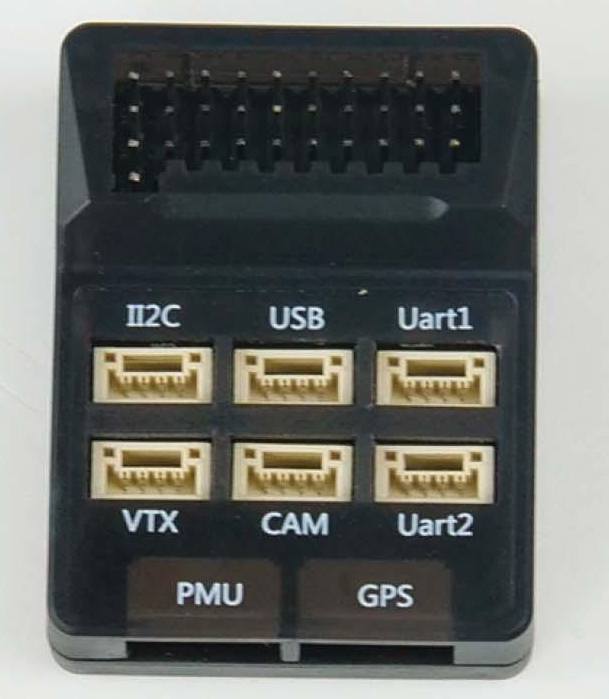
the above image and some content courtesy of HEEWING
Note
- Due to flash memory limitations, this board does not include all ArduPilot features.
See Firmware Limitations for details.
Specifications
Processor
STM32F405RGT6 ARM (168MHz)
AT7456E OSD
Sensors
ICM-42688P IMU (accel, gyro)
SPL-06 barometer
Voltage & current sensor input
Power
2S - 6S Lipo PMU unit providing:
88A Current monitor
9V/3A BEC for powering Video Transmitter
5V, 5A BEC for internal,servos, and peripherals
Interfaces
9x PWM outputs DShot capable
1x RC input/ can be used as full UART with BRD_ALT_CONFIG = 1
4x UARTs/serial for GPS and other peripherals
I2C port for external compass, airspeed, etc.
USB-C port on remote dongle
Note
the original version has no logging capability. The V2 version has an internal flash (i.e no SD Card) for logging, etc.
Size and Dimensions
44.3mm x 34.3mm x 13.7mm
??g
Where to Buy
User Manual
Pinouts
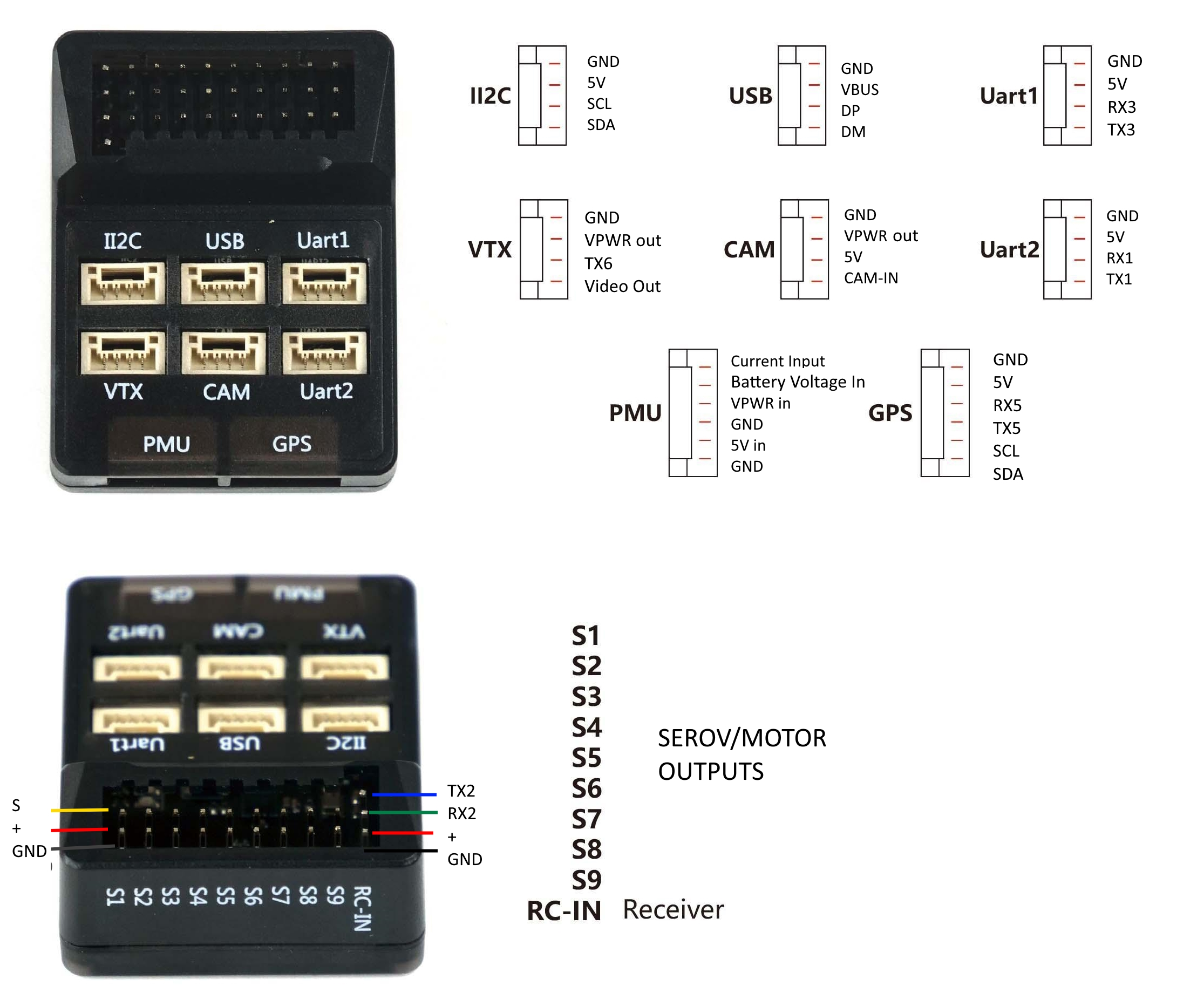
Note
servo/motor power rail supplied from 5V PMU input. Disconnect any ESC BEC’s power lead
Default UART order
The UARTs are marked Rn and Tn in the above pinouts. The Rn pin is the receive pin for UARTn. The Tn pin is the transmit pin for UARTn.
SERIAL0 -> USB
SERIAL1 -> UART3 (marked UART1 on casing, DMA-enabled)
SERIAL2 -> UART1 (marked UART2 on casing, DMA-enabled)
SERIAL3 -> UART5 (GPS)
SERIAL4 -> UART4 (not pinned out)
SERIAL5 -> UART6 (TX only on VTX connector)
SERIAL6 -> UART2 (RCIN RX-only or RX/TX with BRD_ALT_CONFIG = 1, DMA-enabled)
Serial protocols shown are defaults, but can be adjusted to personal preferences.
Servo/Motor Outputs
The HEEWING F405 supports up to 9 PWM outputs. M1-M2, M5-M6 and M9 support bi-directional dshot. All outputs support dshot although M3-4 are not recommended for this purpose as they share resources with I2C.
The PWM is in 4 groups:
PWM 1 and 2 in group1
PWM 3 and 4 in group2
PWM 5 and 6 in group3
PWM 7-9 in group4
Channels within the same group need to use the same output rate. If any channel in a group uses DShot then all channels in the group need to use DShot.
RC Input
The RCIN pin, is passed by an inverter to RX2 (UART2 RX), which by default is mapped to a timer input instead of the UART, and can be used for all ArduPilot supported receiver protocols, except CRSF/ELRS and SRXL2 which require a true UART connection. However, FPort, when connected in this manner, can provide RC without telemetry.
To allow CRSF and embedded telemetry available in Fport, CRSF, and SRXL2 receivers, the RX2 pin can also be configured to be used as true UART2 RX pin for use with bi-directional systems by setting the BRD_ALT_CONFIG to “1” so it becomes the SERIAL2 port’s RX input pin.
With this option, SERIAL6_PROTOCOL must be set to “23”, and:
PPM/SBUS is not supported.
FPort requires connection to TX2 and RX2 via a bi-directional inverter. See FPort Receivers.
CRSF also requires a TX2 connection, in addition to RX2, and automatically provides telemetry.
SRXL2 requires a connection to TX2 and automatically provides telemetry. Set SERIAL6_OPTIONS to “4”.
Note
UART2 is configured by default for serial receivers. You can also have more than one receiver in the system at a time (usually used for long range hand-offs to a remote TX). See Multiple Radio Control Receivers for details.
Any UART can be used for RC system connections in ArduPilot also, and is compatible with all protocols except PPM (SBUS requires external inversion on other UARTs). See Radio Control Systems for details.
OSD Support
The HEEWINGF405 supports using its internal OSD using OSD_TYPE 1 (MAX7456 driver). External OSD support such as DJI or DisplayPort is supported using any free UART. See MSP OSD for more info.
Battery Monitor Configuration
These settings are set as defaults when the firmware is loaded for use with its accompanying PMU. However, if they are ever lost, you can manually set the parameters:
Enable Battery monitor.
BATT_MONITOR =4
Then reboot.
BATT_VOLT_MULT 7.71
BATT_AMP_PERVLT 26.7
Connecting a GPS/Compass module
This board does not include a GPS or compass so an external GPS/compass should be connected in order for autonomous modes to function.
Firmware
First Versions
The first version of the board does not come a correct Ardupilot bootloader (it may at some future point) so it cannot be upgraded with new versions of Ardupilot firmware. ANd cecause it has not boot pin exposed, DFU loading is not possible.
Instead a “transitional” firmware can be used and loaded like normal ArduPilot firmware (this is rev 4.3.7 Plane firmware) as a custom firmware file in Mission Planner.
This firmware contains the correct bootloader and it can be installed using the Mission Planner: SETUP->Install firmware “Bootloader Update” button after this firmware is loaded. From then on you can load any ArduPilot future firmware versions you desire, normally.
Firmware for this board can be found here in sub-folders labeled “HEEWING-F405”.
V2 Version
The upcoming V2 version with internal flash logging should ship with a correct bootloader with ArduPilot firmware installed. Updating firmware can be done normally with Mission Planner or other GCS.
Firmware for this board can be found here in sub-folders labeled “HEEWING-F405v2”.