Optitrack for Non-GPS Navigation
This article explains how a OptiTrack motion capture system can be used as a short-range substitute for a GPS allowing position control modes like Loiter, Guided, RTL, and Auto indoors.
Note
You will need a recent version of ArduPilot on your copter (Copter-4.0 or above).
Required hardware
Please refer to OptiTrack build your own tool for all hardware required to setup a motion capture system.
Note
In order to track the both location and orientation of a drone, you need at least 4 markers.
Motion capture system setup
Please refer to OptiTrack quick start guides for hardware and software setup. When you set the ground plane, do not forget to mark the origin and the axis. The positive X will point to the “north” of our indoor flight environment (because we do not use compass, it do not need pointing to the real/magnetic north)
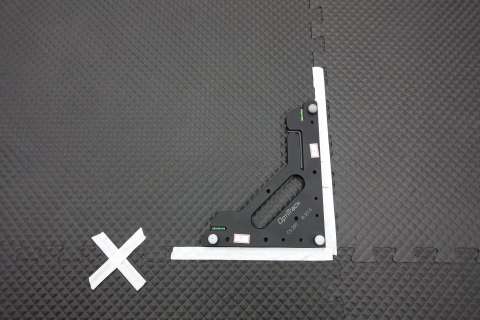
Mark motion capture system coordinate system using tape
Required software
Prepare the drone
Warning
It is highly recommended that use small drone for indoor flight and deploy cage in your test flight environment.
Tip
If you are looking for a small drone for indoor flight test, Skyviper V2450 GPS drone or its successor journey GPS drone is a good choice. It is very affordable and running ArduPilot out-of-box. You can easily flash it with custom build ArduPilot. If you prefer custom build small drone, there is a very good discuss here. The RTF quadcopter frame used in another example video is available from sdmodel.
First, you need to place markers on the drone. It is very important to place markers so that they form a stereoscopic, asymmetrical shape. Please refer to OptiTrack rigid body marker placement for details.
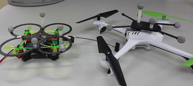
Place markers on the drone
Then, put the drone in the ground plane and align it with X axis of motion capture system. The drone should heading to positive X direction.
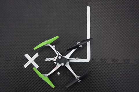
Align the drone with X axis
Select all markers in Motive and create a rigid body from them. Please refer to OptiTrack creating rigid body for details
Configuration the drone
set AHRS_EKF_TYPE to 3 , EK3_ENABLE to 1 and EK2_ENABLE to 0
set COMPASS_USE, COMPASS_USE2, COMPASS_USE3 to 0. It prevents ArduPilot from using compass, because there are many sources causing electromagnetic interference in indoor environment.
set VISO_TYPE to 1
set VISO_POS_M_NSE to 0.3 or lower to increase the weighting of position measurements from motion capture system.
set VISO_YAW_M_NSE to 0.2 or lower
set EK3_SRC1_POSXY to 6
set EK3_SRC1_POSZ to 6
set EK3_SRC1_YAW to 6
set EK3_SRC1_VELXY to 0
set EK3_SRC1_VELZ to 0
Send data to the drone
Start MAVProxy and connect to your copter. Inside MAVProxy load optitrack module with:
module load optitrack
You need to set tracking rigid body id to match your setting in Motive:
optitrack set obj_id RIGID_BODY_STREAMING_ID
If you set Motive data streaming local interface to other than loopback , it is required to configure optitrack module with:
optitrack set server SERVER_IP_ADDRESS
optitrack set client CLIENT_IP_ADDRESS
Note
The coordinate system of both Motive and ArduPilot are right-handed. While Z axis of ArduPilot is pointing down, Y axis of Motive is pointing up.
After all parameters is set, start sending pose to ardupilot:
optitrack start
Ground testing
Connect the drone to MAVProxy
Start Motive and make sure data streaming is turned on.
Load and start optitrack module.
After starting the OptiTrack stream, verify that the position reported by ArduPilot closely matches the position shown in the OptiTrack (Motive) software.
Small offsets (a few centimeters) are acceptable. Large discrepancies indicate a configuration issue such as incorrect axis alignment, origin placement, or rigid body setup.
If you see the following message appearing (initial pos may vary), then the drone is receiving pose data from the Optitrack system.
EKF3 IMU0 is using external nav data
EKF3 IMU0 initial pos NED = 0.1,-0.2,0.0 (m)
EKF3 IMU0 ext nav yaw alignment complete
Flight testing
Take off in AltHold mode and maintain a stable hover. Switch to Loiter but be ready to switch back to AltHold or Stabilize if the vehicle’s position or altitude becomes unstable.
Note
In order to take off in Guided, Auto, or RTL modes, a valid GPS global origin must be set using GPS_GLOBAL_ORIGIN.
The latitude and longitude do not need to be highly accurate, but they must be valid coordinates. It is recommended to use the approximate latitude and longitude of the building or test facility where the motion capture system is installed (for example, obtained from Google Maps). Altitude can be set to zero or an approximate value.
The GPS global origin is only used as a reference frame; all position information comes from the OptiTrack system.