Using a Vicon indoor positioning system
Robotics labs commonly have an indoor flying facility using a Vicon indoor positioning system. These systems use infra-red cameras to give a high rate (200Hz) position and attitude via a network connection. ArduPilot can use this positioning information for precise indoor flight.
Overview
The Vicon system comes with a SDK that provides APIs for accessing the Vicon positioning data. To use the Vicon data with ArduPilot you need a tool which can use this API and map it onto MAVLink packets to send to ArduPilot.
There are two types of MAVLink packets that can be used:
the GLOBAL_VISION_POSITION_ESTIMATE packet, which provides position (NED) and attitude (euler angles).
the GPS_INPUT packet which provides position as latitude/longitude, altitude, velocity (3D) and yaw data.
Right now the best approach is to use GPS_INPUT with the GPS yaw extension as the velocity data provided by the GPS packet is more valuable for good positioning than the attitude information in the GLOBAL_VISION_POSITION_ESTIMATE packet. In the future we will support a combined VISION MAVLink message which will provide position, velocity and attitude in one packet.
Hardware Setup
You will need a low-latency network link from your GCS computer to the copter, and from the GCS to your Vicon server. The recommened method is to use ethernet to the Vicon server and use a ESP8266 WiFi link running mavest8266 on the copter.
Vicon System Setup
The Vicon system should be correctly calibrated. The origin should be set using the calibration wand. In the Vicon Tracker software, the Z-axis (shown in blue) of the Vicon system world frame should point up. We will call the X-axis (red) as North, and the Y-axis (green) as West.
The UAV should have a minimum of 4 reflective markers to ensure an accurate fix. Any reflective surfaces on the UAV should be covered with masking tape to avoid spurious detections.
Place the UAV in the Vicon space so that the forward direction of the autopilot is facing ‘North’. (Figure 1)
In the Vicon Tracker, select all of the markers and create a new object for the UAV. The coordinate frame of the UAV should then be aligned with the Vicon world frame, so that X is forward, Y is Left and Z is up. (Figure 2)
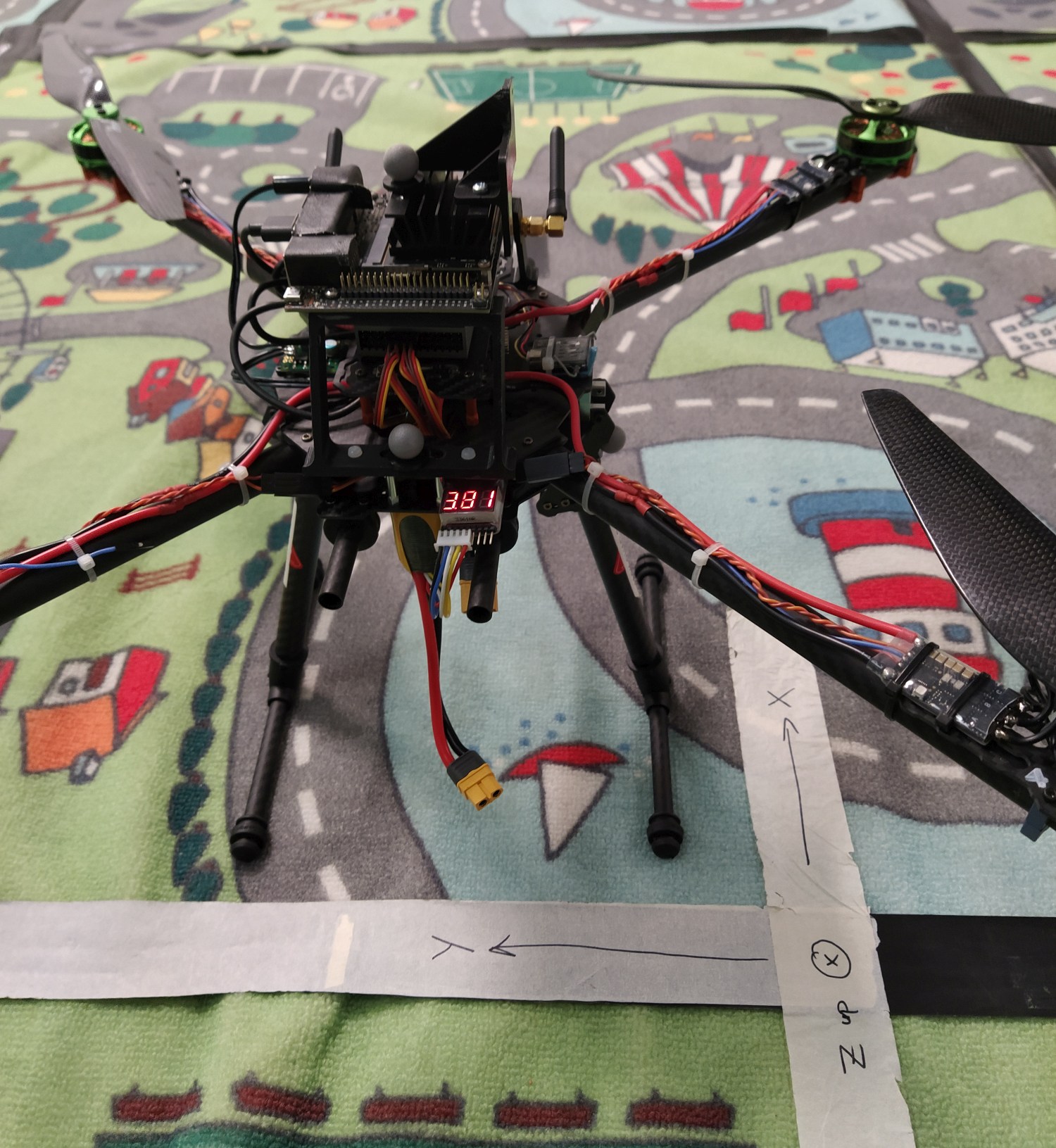
Figure 1: Example of how UAV should be positioned when creating the Vicon Object. The forward direction is aligned with the X-axis.
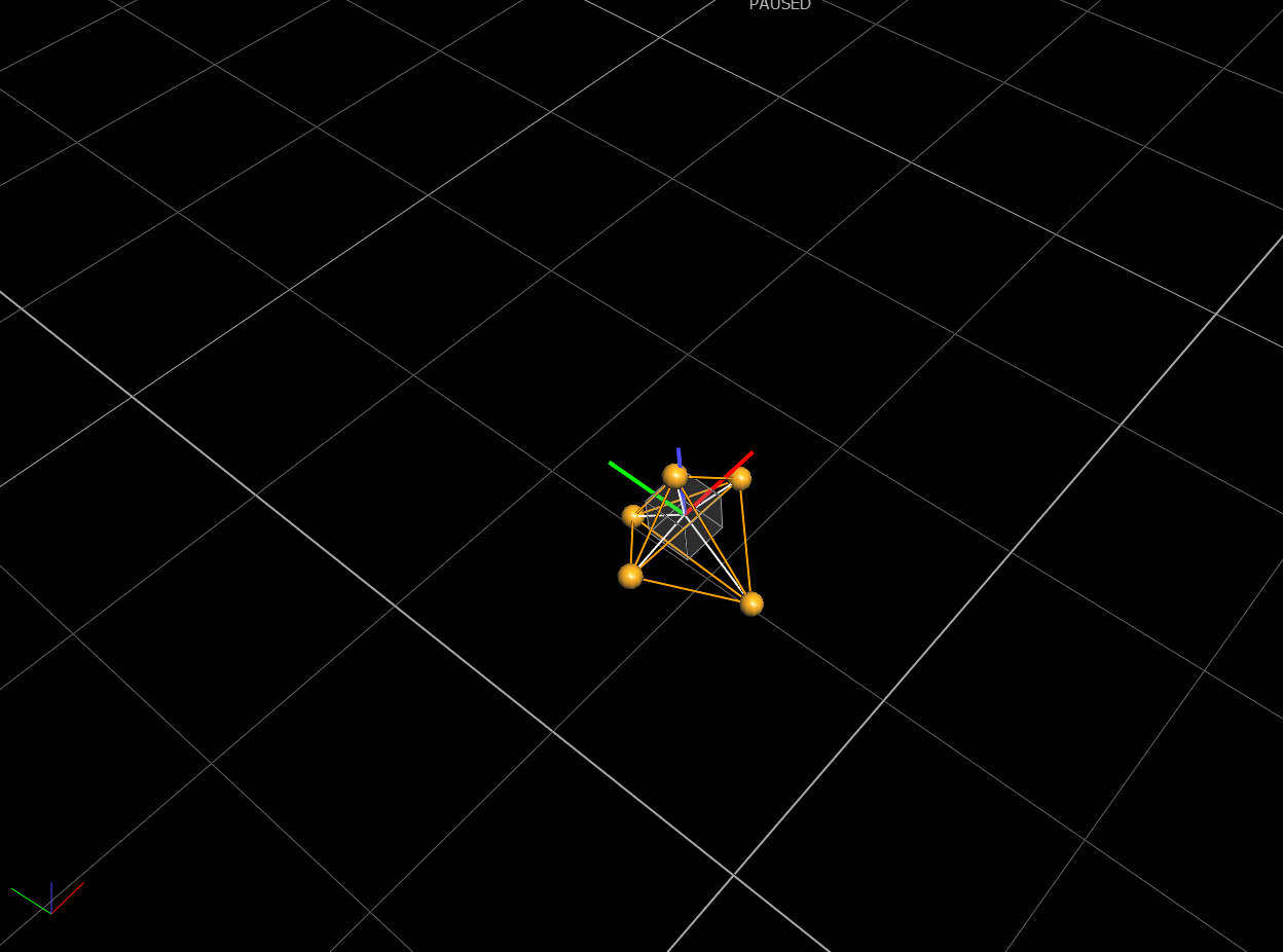
Figure 2: Screenshot from Vicon Tracker software, showing world coordinate frame (bottom left) aligned with UAV coordinate frame. The origin of the object frame should be approximately where the autopilot is located.
Warning
These coordinate frame conventions apply to MAVProxy version 1.8.36 and above. Ensure you are using an up-to-date version.
Software Setup
You will need a recent version of ArduPilot on your copter. As of September 2019 it is recommended that you use ArduPilot master. The recent version is needed to give support for yaw data in the GPS_INPUT MAVLink message.
The setup described below uses the vicon module in MAVProxy to feed the Vicon data to your vehicle over MAVLink.
pyvicon
You will need to install the pyvicon python package, using a python version of at least 3.6. To install pyvicon you will need to also install the Vicon SDK, version 1.10 or later, from ViconDataStream SDK
Note that pyvicon does not build with python2.
Once you have the SDK setup, you should install pyvicon like this:
python3 setup.py build install --user
You will also need to add $HOME/.local/bin to your $PATH.
pymavlink
You will need a pymavlink version of at least 2.3.8. Install with:
python3 -m pip install --upgrade --user pymavlink
MAVProxy Setup
You will need MAVProxy version of at least 1.8.36. Install with:
python3 -m pip install --upgrade --user mavproxy
You will also need some other python3 libraries, install with:
sudo apt-get install libgtk-3-dev
python3 -m pip install --user pathlib2 wxpython matplotlib
Next you should put the IP address of your vicon server in your /etc/hosts file, so that you can do “ping vicon”. The name ‘vicon’ is used as the default hostname in the MAVProxy vicon module.
Connecting
Setup your copter with the WiFi link running at baudrate 921600 and with MAVLink2 enabled. If your WiFi adapter is on Telem1, then you will need to set:
SERIAL1_PROTOCOL=2
SERIAL1_BAUD=921600
Next start MAVProxy like this:
mavproxy.py --master :14550 --aircraft MyQuad --console --map
For more details see the MAVProxy documentation
Key Parameters
You should set the following key parameters:
EK3_ENABLE=1
EK2_ENABLE=0
AHRS_EKF_TYPE=3
EK3_GPS_TYPE=0
EK3_MAG_CAL=5
EK3_ALT_SOURCE=2
GPS_TYPE=14
GPS_DELAY_MS=50
COMPASS_USE=0
COMPASS_USE2=0
COMPASS_USE3=0
After setting these parameters you should reboot your copter.
Starting Vicon
Inside MAVProxy load the vicon module with:
module load vicon
If it doesn’t load correctly then enable debugging with “set moddebug 3” then try to load the module again.
Once loaded you set set vicon parameters with “vicon set”. Once you are happy with the parameters then do “vicon start”
The MAVProxy console will then give status information for the Vicon, showing position, attitude and messages rates. The vehicle should also get GPS lock. It will show up at the GPS coordinates in the vicon module settings.
Checking Orientations
Use the Vicon status line in the MAVProxy console to check that you have the right orientation in the data coming from the Vicon. The VPos data is in NED format in meters. The VATT data is euler angles of roll, pitch yaw. Carefully check that these values are consistent while you rotate and move the vehicle before proceeding.
Test Flight
You should see ArduPilot first report that EKF3 gets yaw alignment, and then that it is using the GPS. After that you should be able to arm and fly.
For a first test flight STABILIZE or ALT_HOLD mode is recommended. Then get the flight log from the microSD card and check that the EKF3 innovations are low. The position, velocity and yaw normalised innovations should all be low (below 0.1).
Once you have confirmed low innovations you can try a flight in LOITER mode.
Tuning
If you have significant vibration then you will likely want to de-weight the accelerometers and instead tell the EKF to use the vicon data more. Try setting EK3_ACC_P_NSE to 2.0 to de-weight the accelerometer data. You may find this helps with position and height hold.
For indoor flightw with a Vicon setup and a small quad you can push up the accelerations and yaw rate to much higher value than are used in a normal quad. Some suggestions for a small racing quad are:
INS_GYRO_FILTER=60
INS_ACCEL_FILTER=30
ATC_ACCEL_Y_MAX=100000
ATC_SLEW_YAW=15000
Circle Mode
A very useful mode for testing accuracy of flight is Circle Mode <circle-mode>. To use it indoors try:
CIRCLE_RADIUS=100
CIRCLE_RATE=40
You should also set your RTL_ALT nice and low in case you hit a failsafe, or configure a instant disarm switch on your transmitter for when things go wrong.
To fly in circle mode take off in LOITER and then move so you are 1m from the center of the room, pointing towards the middle of the room. Then switch to Circle mode and the vehicle should start circling, keeping its nose pointed at the center of the circle. You can try pushing up CIRCLE_RATE to higher values (in degrees/second) as you get more confident. The video at the top of this page has CIRCLE_RATE=150 for a 150 degree/second circle.