Bluetooth Telemetry radio
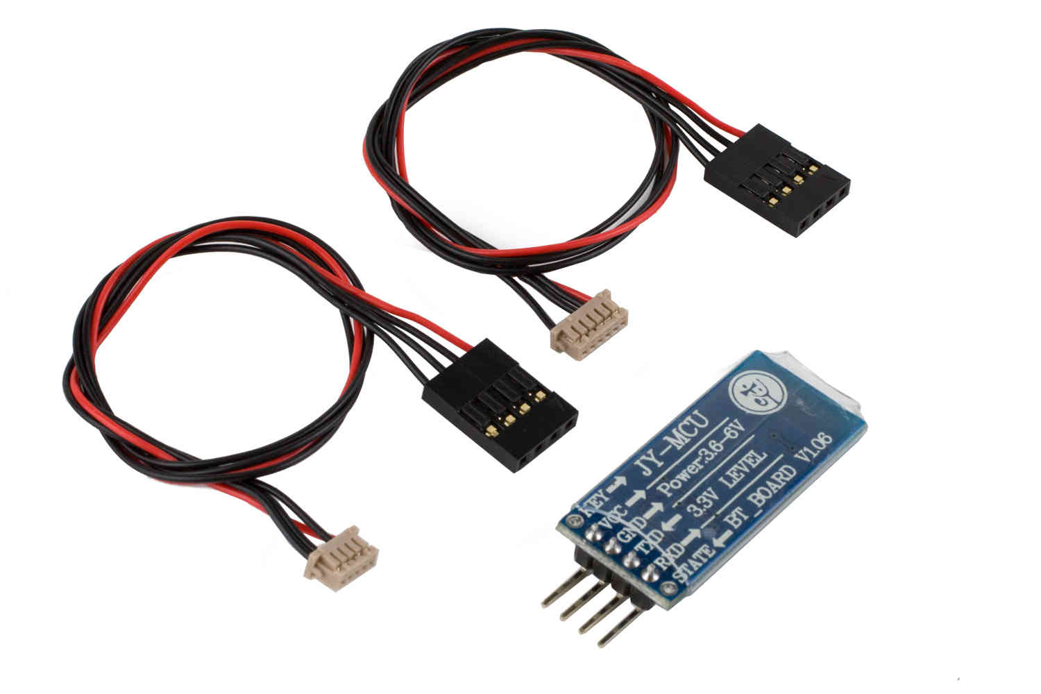
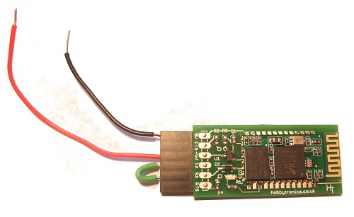
` A Bluetooth Data Link , such as an HC-06 module can be used to connect your Pixhawk (or other controller) to your Bluetooth enabled PC or Android Ground station at distances up to 50m.
Note
this module’s baud rate usually must be changed from its default of 9600 to 57600 for use with ArduPilot. This is usually accomplished connecting it to a FTDI USB-serial adapter and using AT commands in a terminal program like Putty. See the last section of this page for more information on setting up the HC-06.
Connecting to the Autopilot
The Bluetooth data link often comes with both a DF13 6 pin and 6-to-5 pin connector which make it easy to connect to the autopilot’s serial ports. Note that any unused serial port on the autopilot can be used.
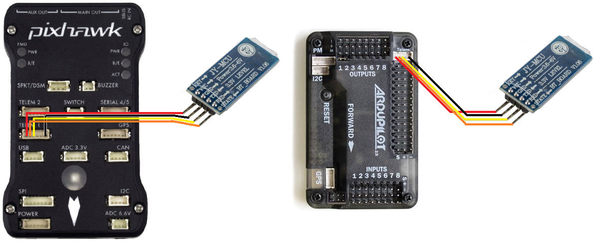
Once you have connected the Bluetooth data link you can power up the autopilot. It is OK to use USB connected power while using the Bluetooth module connected to the autopilot as long the the total power of ALL autopilot connected peripherals do not exceed the computer’s capability (usually 1A)
Bluetooth data link’s LEDs:
Red LED blinks at 1hz : device is working, not connected
Red LED blinks at 0.5z : pairing
Red LED solid : connected
AutoPilot Setup
On the autopilot SERIAL port that the module is attached (we will use SERIAL2, sometimes labeled TELEM2, for the following), make sure it’s parameters are set as:
SERIAL2_BAUD = 57 (57600)
SERIAL2_PROTOCOL = 2 (MAVLink2)
Connecting with Mission Planner
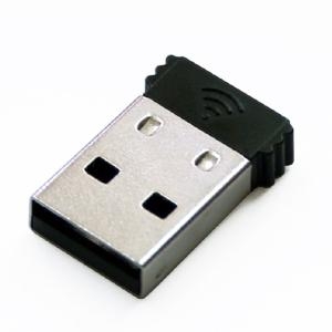
Many PCs and Laptops have bluetooth adapters built in but if not then you can use a generic USB Bluetooth dongle (pic above) or use an additional Bluetooth data link connected via an FTDI Cable.
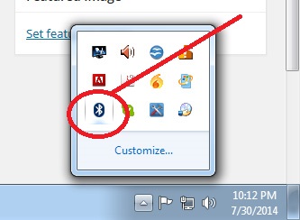
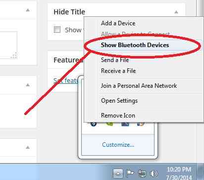
After first making sure your autopilot is powered on, and your PC’s bluetooth dongle is plugged in and installed, click on the Windows task bar’s little up triangle (aka “show hidden icons”) which should be on the bottom right of the screen.
The “hidden icons box” should appear. Right-mouse-button-click on the BlueTooth icon and select “show Bluetooth devices”
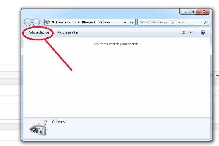
Windows should bring up the devices box. Any devices you may already have connected by Bluetooth will be in this box. If you have not connected any BT devices before this box will be empty. Select “Add a device”.
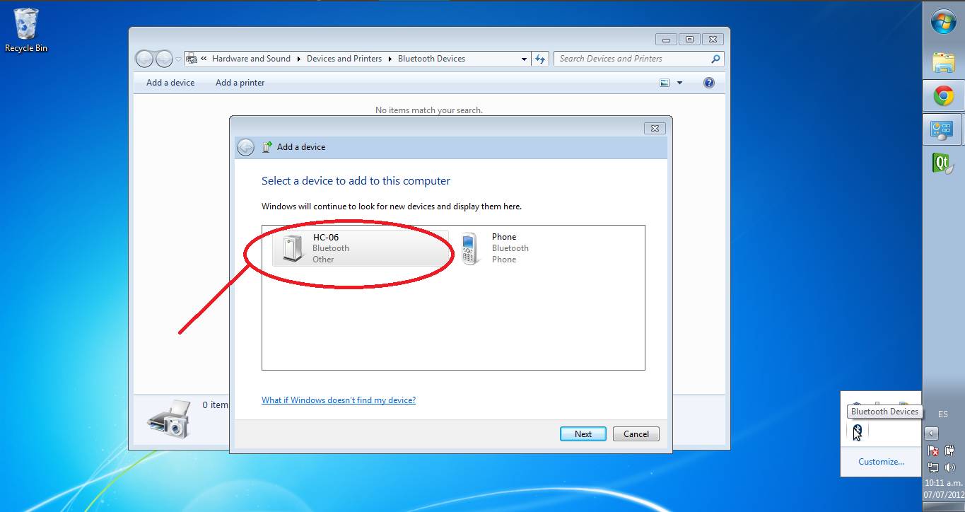
Windows will search for BT devices for you. If you have any BT devices turned on they will show up here (like perhaps your cell phone) ignore any other devices and select the HC-05 or HC-06 (or Linvor) .
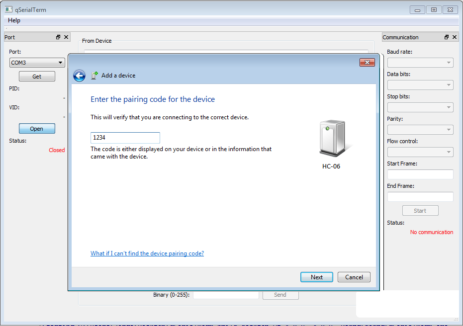
Select Paring using device code.
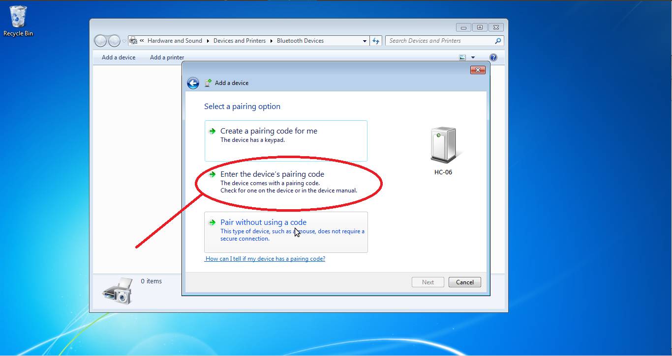
Enter the device code (1234 or 0000) this is the default code.
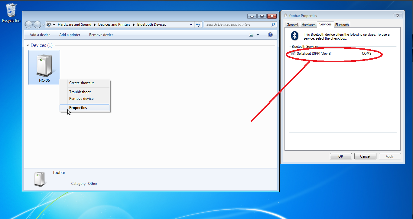
Once paired right click the device and select “properties” The check box for Comm Port SPP should be checked (also note the com port number).
In device manager select Com Ports
Choose the comm port you noted in the above step.
Right click and select “properties”
Change baud rate to 57600
Your Bluetooth device should now be ready and you can connect to the port presented by the BT adapter in Mission Planner at the baud rate of 57600 (red LED steady on and not flashing)
Connecting From your Android ground station
These instructions will show you how to connect to your vehicle from Android device with a GCS app (like QGC, etc.) using the Bluetooth module.
Open the Android device’s settings panel and turn Bluetooth connectivity ON (usually by sliding a slider to the right). In the same settings screen click on “Bluetooth” which should cause a list of AVAILABLE DEVICES to appear
Power the vehicle and the “HC-06” (or whatever name you have changed it to below) device should appear. Click on it and enter “1234” or “0000” as the PIN to pair with the device, then select OK.
The device will appear under “PAIRED DEVICES”
Then start you Android based ground control station and connect the Bluetooth data stream. Some systems will automatically ask you select the GCS application to use the BT connection. Sometimes you will have to explicitly setup the BT connection within the GCS application.
Connecting with Linux to any Ground Station
To bind the Bluetooth module to a ground station like MAVProxy or Mission Planner you need to pair it to your machine. With Linux the easiest way is to use rfcomm, this is a Linux utility that allows you to bind a Bluetooth device to a serial port so you can connect to it like you have a USB cable plugged in.
Connect the Bluetooth device to your laptop. The easiest way to do this is through your GUI, I am using the settings that are built in to GNOME. You need to put it in pairing mode then pair it, you will be prompted to enter a code; the code is often 1234 or 0000, but see below for more info.
You need to find the MAC address of your module, you can do this by using CLI tools but you can also find it in your GUI.
To bind the Bluetooth device to a serial port you can use a tool like rfcomm, this is a Linux tool (see the man page). It is quite simple to use, you first need to run
sudo rfcomm bind /dev/your_serial_port_of_choice XX:XX:XX:XX:XX:XXwhere the last argument is your MAC address. For my module the command looked likesudo rfcomm bind /dev/rfcomm24 04:25:04:12:0A:16. This is not persistent between reboots, so after a reboot you should usesudo rfcomm release allwhich will release all bindings, then you can re-pair with the previous command.Connecting to the device is as easy as connecting to a normal serial device. For MAVProxy you can run
mavproxy.py --master=/dev/rfcomm24and you are connected.
How to Change Baud Rate, Device Name and Device PIN
You will need a FTDI to USB cable to change any of the configurations of the device (not supplied). Often the baud rate must be changed from 9600 to 57600.
To change the above you need a “Terminal” emulator program. You can not use “Putty” (a popular serial port tool) because it will not accept “line” commands. The Bluetooth Modules read the input at a rate of once per second therefore you must use an emulator that will allow you to input an entire line before hitting “send”. You can use the Arduino IDE to send commands to the com port if you are familiar with that. I use “Advanced Serial Port Terminal” but any terminal emulator that allows you to type in a line of text before hitting send will work just a good.
See this video for an example.
Change the baud rate
The index after the command AT+BAUD corresponds to the following baud rate:
1—-1200bps
2—-2400bps
3—-4800bps
4—-9600bps (usually the default)
5—-19200bps
6—-38400bps
7—-57600bps (how we setup the autopilot to communicate)
8—-115200bps
There are additional baud rates. Warning! do not set these baud rates unless you have a special fast UART chip. If you don’t know do not use these rates they are beyond the standard PC UART speed and once set you will loose communication with the device and the only way to contact the device after that will be with a high speed UART. (these are for reference only)
9—-230400bps
A—-460800bps
B—-921600bps
C—-1382400bps
The change of Baud rate takes effect immediately after the command is sent. So if you want to keep configuring the Bluetooth module, you need to set the Baud rate of your terminal program to the new Baud rate the Bluetooth is using. To test it, send AT again, you should receive ‘OK’
Change the Device Name
This example show you how to change the name of the Bluetooth module to ArduPilot: In the terminal program, send the command (case sensitive):
AT+NAMEArduPilot
The Bluetooth should reply:
OKsetname
Change the Device PIN
The following example shows how to change the pairing code to 5566 In the terminal program, send the command (case sensitive):
AT+PIN5566
The Bluetooth should reply:
OKsetPIN
Troubleshooting
You can test the device by making a loopback from TX to RX.
Open your terminal program select the correct comm port and in terminal type anything you like. If you see the test displayed then your device is working properly. If you do not see the text you typed and you have selected the correct comm port and your device is paired and connected (red LED solid on not flashing) then you may have a problem with your device.
Specs
Dimensions : 1.4” x 0.6” x 0.17”
Weight 9.6 g (0.3 oz)
Operation voltage: 3.6 to 6 V
I/O level: 3.3 V
Typical -80dBm sensitivity
Up to +4dBm RF transmit power
UART interface with programmable baud rate
Default baud rate: 57600
Supported baud rates: 1200, 2400, 4800, 9600, 19200,38400, 57600, 115200, 230400, 460800
Pairing code: 1234 or 0000
Auto-connect to the last device on power as default
Permit pairing device to connect as default
Integrated antenna
Range: 50 m