Mocking an Airspeed Sensor for Bench Testing
This article explains how you can use a potentiometer with an autopilot in order to simulate the input from an Airspeed Sensor. This is very useful for ground testing.
Overview
If your aerodynamic surfaces (i.e. auto flaps, ailerons, elevators, elevons, etc.) are geared or actuated with airspeed, it may be helpful to ground test them on your aircraft by sending the autopilot a specific airspeed.
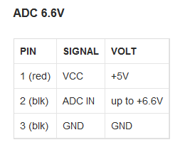
To do this you must apply a voltage to an analog input pin designated as the analog airspeed input. On a Pixhawk you can plug a potentiometer into ADC 6.6v (pin 15) or ADC 3.3v (pin 11). If you are using an I2C airpseed sensor you will temporarily configure your autopilot to use the analogue port.

Required parts
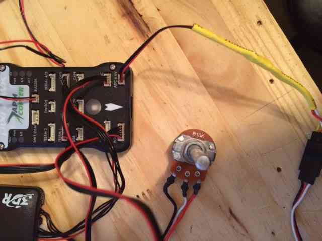
You will need a DF-13 cable and a simple potentiometer like this or this. Either a B10K and B5K potentiometer can be used to set speed from 0 to as much as 90 m/s.
Pixhawk Configuration and Settings
Once the DF 13 cable is connected to the potentiometer, plug it into the
ADC 6.6v port.
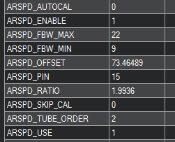
Open your Ground Control Station (GCS) of choice, and change the
ARSPD_PIN parameter to Pin “15” as shown below.
Reboot your Pixhawk to allow this parameter change to have an effect. Airspeed will reset to 1-3 m/s after the restart and initialization is complete. Adjust the pot to set your desired speed.
Note
If you are using an I2C airspeed sensor - remember to re-enable it!
Set the ARSPD_PIN
parameter to 65, and cycle the autopilot power to ensure the I2C airspeed
properly initializes. Check you get the normal 1-3 m/s noise on the
airspeed display.