Omnibus F7
Above image and some content courtesy of myairbot.com
Note
Support for this board is available with Copter-3.6.0 (and higher)
Note
Due to flash memory limitations, this board does not include all ArduPilot features. See Firmware Limitations for details.
Specifications
Processor
STM32F745VG ARM
1MB of Flash memory
Sensors
InvenSense MPU6000 IMU (accel, gyro) with vibration isolation
InvenSense ICM20608 IMU (accel, gyros, compass) with vibration isolation
BMP280 barometer
Interfaces
UARTS
PWM outputs
RC input PWM/PPM, SBUS
I2C port for external compass
USB port
Built-in OSD
Voltage and Current sensing inputs (Needs external current sensor)
Size and Dimensions
36mm x 36mm
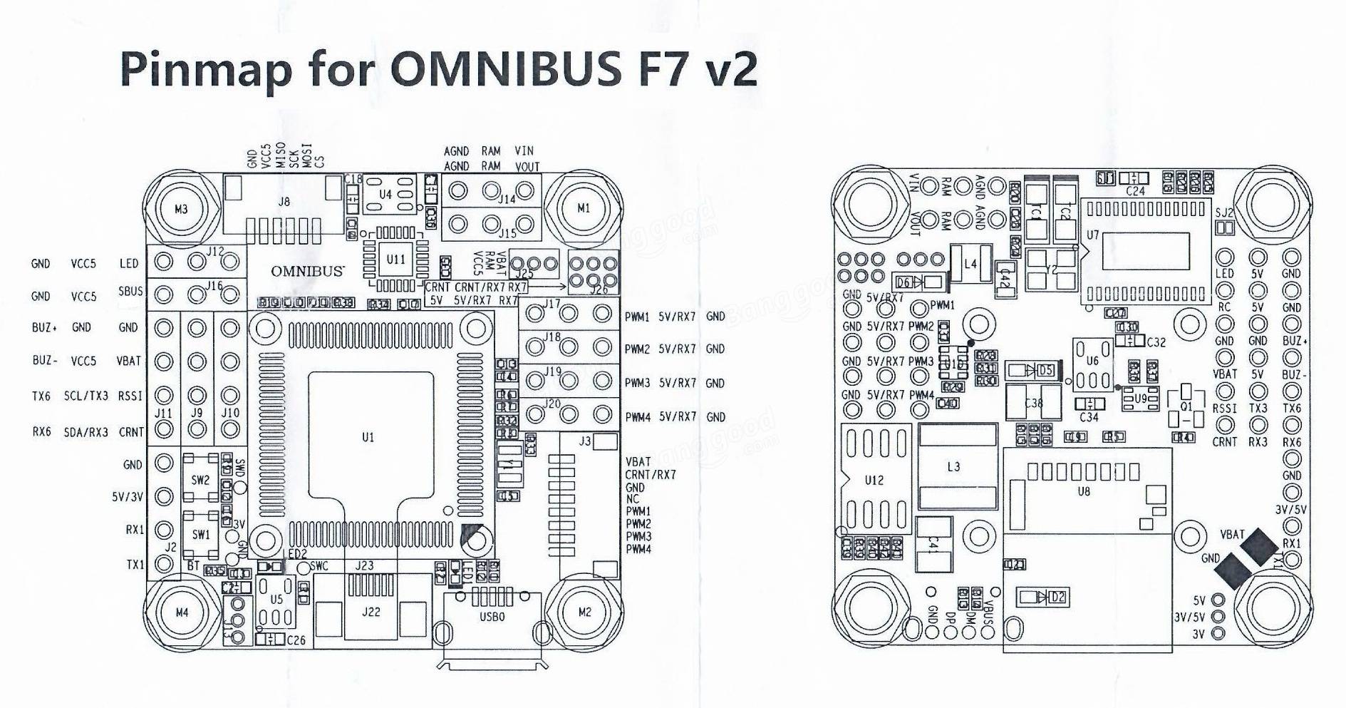
Board Connections
GPS is attached to UART6
Telem is available at UART 1
The shared UART3/I2C pins are enabled by default only for I2C operation to allow external compass or digital airspeed sensor attachment.If at least one device attached externally does not have pull-up resistors, then 2K ohm pull-up resistors will need to be added externally to these pins.
By setting BRD_ALT_CONFIG to 2, those pins change from I2C to UART3 TX and RX pins.
Default UART order
SERIAL0 = console = USB
SERIAL1 = Telemetry1 = USART1
SERIAL2 = Telemetry2 = USART3 if BRD_ALT_CONFIG = 2, otherwise these pins are used for I2C pins (firmware 4.1 or later)
SERIAL3 = GPS1 = USART6
SERIAL4 = GPS2 = USART2 (RX only if BRD_ALT_CONFIG = 1, otherwise this pin is used for RC input labeled SBUS on board)
SERIAL5 = USER = UART7 (RX only, in V2 only)
SERIAL6 = not assigned
Serial protocols can be adjusted to personal preferences.
RC Input
RC input is configured on the SBUS (UART2_RX) pin. It supports all RC protocols, however for FPort BRD_ALT_CONFIG should be set to 1 with SERIAL4_OPTIONS=15 as described in the FPort section.
Configuration
Enable Battery monitor with these settings :
BATT_MONITOR=4
Then reboot.
BATT_AMP_OFFSET 0.008
BATT_VOLT_MULT 10.925
BATT_AMP_PERVLT 58.0 (note, this value is valid if using Matek Systems FCHUB A5 current sensor)…will need to be calibrated to match actual current if using another make of PDB board)
Dshot capability
All motor/servo outputs are Dshot and PWM capable. However, mixing Dshot and normal PWM operation for outputs is restricted into groups, ie. enabling Dshot for an output in a group requires that ALL outputs in that group be configured and used as Dshot, rather than PWM outputs. The output groups that must be the same (PWM rate or Dshot, when configured as a normal servo/motor output) are: 1/2, and 3/4.
Where to Buy
available from multiple retailers including myairbot.com