Mission Planner GPS-based Antenna Tracking
This article explains how to build a GPS-based Antenna Tracker that uses the Mission Planner GCS to provide directional/tracking information for a servo-driven directional antenna.
Note
This approach requires that the GCS is running on a PC that has access to GPS information. See Antenna Tracking for other options.
Overview
An Antenna Tracker is a system that tracks the location of a vehicle and uses this information to aim a directional antenna.
The tracker described in this article uses the Mission Planner to determine the direction to aim the tracker using the position of the GCS and the current position information from the vehicle. The tracker requires that your vehicle is providing GPS telemetry, and you will also need a Servo Controller card in order to drive the servos from Mission Planner.
Parts
This is a list of the main components needed to build this tracking system (it is not all inclusive with things like screws, glue etc.)
Body frame, custom built or off the shelf
Antenna(s)
Two servos
Servo controller card, like the Maestro
Tripod (or other mounting device)
Battery
(Optional, recommended:) BEC, cooling fan, battery low voltage device.
The function of the parts is described in the following sub-sections:
Body
You will need a body that can support the tremendous weight of your antennas. 4 lbs is a “tremendous” amount of weight to throw around depending on what torque and what materials your servos are sporting. This is the one I chose to use for this guide. It currently is holding two patch antennas each weighing about 12oz. You can design your own body, but you should have a CNC machine as part of the solution as any inaccuracies could make it not track correctly and there goes your aircraft. All wood construction is fine for two antennas while metal bodies could be used to make minimal structures or to increase durability.
A special mention of gears needs to be addressed. The body I used has gears. Gears do a couple of things that you might find useful. First they can “convert” torque into distance (even change the angle the force acts through) and second they can increase or decrease the speed of rotation. Sometimes you can use them to make your body semi detachable from the servo like the example one I gave above, which is very very useful. You can also get by without having one at all.
When choosing a gear, keep in mind a few things. First, the further out you go from the center of your servo to the center axis of rotation of your AT the less torque will reach it. All servos have a rating like 10 kg-cm or 100 oz-in, that means that that particular servo has 10kg of force when you measure that force at exactly 1 cm from the center of the servo, likewise for 100 oz-in, 100 ounces of pressure measured at 1 inch from the center of the servo shaft. So, the further out you go, say, 2 inches you drop the torque felt at that distance by half (because you doubled the distance through which the force acts) which would be 5 kg or 50 oz for our example.
The speed changes based on the diameter and number of teeth your gearing has. A rule of thumb is the bigger the gear the slower it will turn and the number of teeth it has is related to the size of the gear. So, a big gear with 44 teeth meshing with a gear half its diameter and having 22 teeth with make the smaller gear rotate at twice the speed that the big gear is rotating. You just converted torque into speed.
Antenna
You need to decide which antennas you are going to use. Frequency is HUGE on this. In fact, frequency selection is a guide in and of itself. Some antennas claim usability in a range of frequencies but that is NOT always legit. 915Mhz (aka 900Mhz) is very specific and your antenna could be “tuned” by the factory to “best” receive at 912Mhz and your screwed. Read READ READ the description on the antenna you are looking at. For this guide I choose 1280Mhz (aka 1.2 or 1.3 Ghz) and 915Mhz patch antennas from L-COM. You might be thinking “what about frequency hopping”? Your radio MIGHT try to go outside the “effective” bandwidth (frequency spread your antenna can use well) but if it does it notes the signal drop (aka RSSI, Received Signal Strength Indicator) and will compensate for it. Don’t worry about this, just make sure your antenna is within the correct frequency range you will be using.
Servo
You will need two servos. One for the tilting action and one for the pan action. Tilt is the moving of the antennas only and the pan could move the whole AT or just the antennas depending on how you have yours designed. Servos are actually complicated little devices. I’ll try to be precise as you can use the internet to find more details on servos if you wish. You want a servo that can do at least 110 oz-in of torque for two patch antennas, I’d recommend at least the karbonite materials to ensure it never strips out, but you can get by on the nylon versions.
For the tilt servo get a servo that does 90deg of rotation TOTAL. Different manufacturers explain the total amount of rotation a servo can do in different ways so you must really do your homework. 90deg rotation total is a “standard” servo.
For the pan (this AT in particular, your requirements will vary) I’d recommend at least 150+ oz-in of torque for two antennas and karbonite or better, as in all metal gears. If you can get one, go digital (highly recommend it) as the AT here is capable of small corrective actions and an analogue servo will probably not be able to keep up like a digital servo will. The reason for this overall beefiness is that when your panning range is at the limit of travel your AT will rapidly spin itself around 360deg in order to keep the antennas on target (1:50 second mark as an example). The faster it does this the less time you are out of communication with your aircraft. You can not avoid this behavior if you use the APM Mission Planner as the behavior is embedded in the software. Building an AT that does not care about the pan range is very expensive to do as it starts to involve what are known as slip rings. The military uses them and they are very nice, but very expensive due to the quality of slip ring involved. If you can do this then you avoid cable tangling issues and possibly servo range selection gets easier. For this build the pan action you want is a servo that can do 360deg of rotation. You really don’t need more than that.
Servo Control
You will need something to take the information from your computer (again this build used the APM Mission Planner to drive the AT) and turn those into a signal (numbers really) that your servo can use. The APM MP has two options currently, one for Maestro and one for ArduPilot. The Maestro link is to a SERVO CONTROLLER card and the ArduPilot is both a servo controller and a stripped down autopilot (it is actually the original APM being used as a servo controller card). To be more clear, in some articles the ArduPilot is referred to as the ArduTracker. The Maestro can run up to 6 servos with the input provided by the micro USB cable but you will only use 2 of them plus the power pins. The ArduPilot version uses one of the early versions of the APM called ArduPilot. It is stripped down and cheap, you might have one from years ago, I don’t know much about it, but this is a build that HappyKilmore’s GCS uses and they did a write up on both of them. I used it a lot and you can’t go wrong reading it yourself either! No matter which controller type you use to drive your servos you WILL need to download and install the firmware for them. Maestro came preloaded and it looks like you need to find the firmware for the ArduPilot card from their website or this website’s software library.
Getting the right numbers for your servo controller is vital, use this as a guide. Basically you will find two numbers that bookend the total rotation your servo will do which could be less than what it can do but not more, then you will find the center of those bookends and then you will tell Maestro the “8-bit” range that it should use as commands to send to the servos. It’s way critical to get these right, I lost hair doing it.
Battery
Ok, servos run off of 4.8, 6 or sometimes 7.2V or more. Most of them default to the RC standby voltage of “5V”. This one is running off of 6V. This battery puts out 12.5V when charged fully. If you do not find a way to step down the voltage from your battery to the CORRECT usable voltage for your servo you will fry your servo. Your servo motor might smoke or the little tiny tiny circuit board in it might smoke, either way the reliability of it is gone and you should get a NEW SERVO. If you don’t and it fails in flight, you could lose connection because your AT can not point properly! A BEC (Battery Eliminating Circuit) is what you are looking for here. This project used this one. If you do your homework, you can look up the idle and full load current consumption of your chosen servos and pick a BEC that will handle that load. If you fail to get a BEC that can handle the spontaneous most highest ever load your servo could possibly generate then it will fry and your power to point your AT will be gone, bye bye aircraft.
Battery low-voltage warning device
You don’t have to use this, but I would. It is cheap and could save not only your battery but it will tell you when your AT is about to quit. It is about as loud as a smoke detector going off! Buy a few of these and use them, don’t be cheap like that, seriously.
Video Rx and Tx
Rx and Tx is shorthand for Receiver and Transmitter respectively. It is not in the scope of the AT build guide here to tell you about these but instead it is just to tell you that whichever system you use make sure it can fit to your AT. Your AT is going to get crowded and messy and therefore it can bind on the smallest of things. Binding is bad, ok?
Tripod
You could come up with another thing to use, but that would be tantamount to reinventing the wheel. The higher your AT is the further it can spread its signal. Try to get one that does not have a lot of protrusions like this one has. They will eventually entangle your wires. Pay attention to which type of connector the tripod uses so you can design your AT to link to it. Get one that is sturdy as a nice bit of wind could knock it over and your aircraft goes link dead. Your AT should weigh around 7 lbs max, probably less depending on what you use.
Picture gallery
Connecting the parts
VELCRO AND ZIP-TIES, you can use them to a very large degree here!
1) Connect your servo controller board to your laptop, micro USB to USB for Maestro.
2) Servos connect to the servo controller board. For Maestro it will be servo 0 pin set for pan and servo 1 pin set for tilt.
3) Connect your battery to your BEC which is set at 5V or 6V or whatever your servos can handle (max it out). Connect the BEC to the servo controller board. For Maestro the pin set on the outermost is for the BATTERY power that will drive your servos (the USB cable powers the board). DON’T REVERSE THE POLARITY, buy new stuff if you did.
4) Connect your battery (assuming Li-Po here) to the Low Voltage detection device, pay attention to it.
5) Connect your antennas to your SiK Radio (NEVER TURN ON RADIOS WITHOUT ANTENNA ATTACHED, buy new stuff if you did). Connect antenna to the Video Rx.
6) You will need to splice off the power from the 12V side of the battery connection to feed 12V of power to your Video Rx, get some solder and a wet sponge, do a good job on the connection. Connect the power to your Video Rx.
7) Connect your 3DR 900Mhz radio to the laptop (after you have antenna connected).
8) Use a bunch of zip-ties to secure and bundle all the wires. This is important. If you do a bad job here your AT will bind while its tracking and down goes aircraft.
add VELCRO AND ZIP-TIES to hold everything together
10) Remember to set your end points manually in the Mission Planner for the channels you will use to control pan and tilt, use a PWM value like 1100µs and 1900µs with a midpoint of 1500µs to start. Some 180 degree servo’s can take 600-2400µs but you can damage some servo’s so start conservatively.
Basic use
1) When you get to the airfield you point your AT north, get as close as you can with your eyeball.
2) Normal acceptable calibration for an AT is that you should be within 10deg of North when you point it.
3) This particular body is able to be lifted, which separates the gear of the servo from the smaller gear of the body. This allows it to be oriented very easily. If you don’t have that feature, just pick the thing up after it finishes booting (and therefore is pointing at the default PWM number YOU ASSIGNED when programming the servo controller).
4) You want the tilt to default to the middle of the tilting servo’s travel range, so for a 90deg servo, make it default to 45deg. When you actually USE the antenna for the first time pay attention to the behavior of the tilting and manually adjust it via the sliding bars in Mission Planner. If you’re confident about where it should be you can manually tweak the servo horn. Either method will work but if you use the slider bar you will not overstress the servo when it tries to go PAST it naturally allowed traveling range.
While in flight you can use the slider bars to fine tune the direction the antenna tracker is pointing.
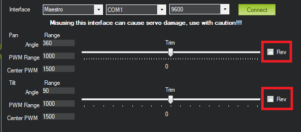
5) If the servos are going in the wrong direction. Try clicking the Rev checkbox to reverse travel direction. You may need to check off Rev before connecting to the servo controller.
Advanced use
Note
This section is an excerpt from a post by Scott Fuller. The original post is here: The expensive but attention grabbing Antenna Tracker)
Usually the first thing I do is power up everything and get a solid GPS lock on the APM. After that I’ll set my plane in front of the antenna tracker and zoom in REALLY tightly in Mission Planner under the Flight Planner window. I’ll then right click and say Tracker Home -> Set here.
Then I’ll drag the antenna tracker pin right on top of home and drop it. That should get me pretty close to where my antenna tracker is placed.
After that I’ll flip over to the Initial Setup tab under Antenna Tracker and pull down the COM port for the Pololu servo controller and go with 9600 baud. When that’s set I hit connect. At that point the tracker should go into motion.
You should be able to move the plane a few meters in front of the antenna tracker should move with it. If you need to reverse the direction it’s pretty self explanatory. The sliders allow you to trim where the antenna needs to be facing. When you start up the system will think you’re facing north. If you’re facing East or West you have to aim accordingly.
You can use Pololu Maestro Control Center to figure out your PWM settings and how far your servos an travel. Usually the PWM setting is (Large Number - Small Number) = PWM. In my case 2000 - 960 = 1040 for pan and 1904 - 1456 = 448 for my tilt. That’ll give me a 45 degree angle for tilt and 360 for pan. You can get these numbers on the status tab in Maestro CC. Be careful NOT to go beyond the recommended travel! On the Servo City gear boxes you’ll hear the POT start to click and the servo will just spin. At that point you get to play the servo centering game.
One thing to note with the Pololu board is you may have to set it into USB Dual Port under Serial Settings. This allows you to connect to the COM port.
Miscellaneous notes
I have included pictures from all angles of my AT (version 2). A few pointers here. Build your AT as light as you can. Get as beefy of servos as you can afford and fit. You can make a wireless version of this AT if you have telemetry radios like the 3DR or the Xbee kits. I don’t know how to do that but it is not going to be anymore complicated than what I have shown here, just more expensive.
Testing is done in two ways, first you setup your AT outside and point it north before you fire it up. Then walk around the AT with your plane with everything linked up as if it was in flight. You need to get at LEAST 60 feet away, try 100ft to make sure. Another way is to load a previously recorded flight from the APM2 logs, set your home position and watch your AT go at it as if it was there.
Test this thing out as best as you can, it is now a critical point of failure for your entire system. I don’t recommend attaching your RC signal (typically your 2.4Ghz) radio that you use to manually control your aircraft. Keep that one unmodified so you have a backup that you can rely on.
Other bells and whistles might include weather vanes, barometers, anemometers, beer can holders, cameras etc. go wild!