Mateksys F405-Wing
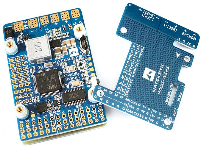
the above image and some content courtesy of mateksys.com
Note
Support for this board is available with Copter-3.6.0 (and higher)
Note
- Due to flash memory limitations, this board does not include all ArduPilot features.
See Firmware Limitations for details.
Specifications
Processor
STM32F405RGT6 ARM (168MHz)
Sensors
InvenSense MPU6000 IMU (accel, gyro)
BMP280 barometer (later models use DPS310)
Voltage & current sensor
Power
9V ~ 30V DC input power
Interfaces
6x UARTS
10x PWM outputs
1x RC input PWM/PPM, SBUS
I2C port for external compass and airspeed sensor
USB port
Built-in OSD
Size and Dimensions
56mm x 36mm x 15mm
25g
See mateksys.com for more detailed specifications and wiring diagrams.
Default UART order
SERIAL0 = console = USB
SERIAL1 = Telemetry1 = USART1
SERIAL2 = empty
SERIAL3 = GPS1 = USART3
SERIAL4 = GPS2 = UART4
SERIAL5 = USER = UART5
SERIAL6 = USER = USART6
SERIAL7 = USER = USART2 (only if BRD_ALT_CONFIG =1)
Serial protocols can be adjusted to personal preferences.
Dshot capability
All motor/servo outputs are Dshot and PWM capable. However, mixing Dshot and normal PWM operation for outputs is restricted into groups, ie. enabling Dshot for an output in a group requires that ALL outputs in that group be configured and used as Dshot, rather than PWM outputs. The output groups that must be the same (PWM rate or Dshot, when configured as a normal servo/motor output) are: 1/2, 3/4, 5/6, 7/8/9 , and 10.
Note
PWM9 is a solder pad, and PWM10 is marked as “LED”
Outputs
The first 8 servo/motor outputs are marked on the board: M1,M2,S3-S8 . S9 is a solder pad on the board, and S10 is connected to the pin marked LED in ArduPilot’s definition. Using S10 allows the easy grouping for odd numbers of motors with a common DShot or PWM frequency without sacrificing the use of an output for servo use due to rate issues (see above Dshot discussion).
RC Input
The SBUS pin, is passed by an inverter to R2 (UART2 RX), which by default is mapped to a timer input instead of the UART, and can be used for all ArduPilot supported receiver protocols, except CRSF/ELRS and SRXL2 which require a true UART connection. However, FPort, when connected in this manner, will only provide RC without telemetry.
To allow CRSF and embedded telemetry available in Fport, CRSF, and SRXL2 receivers, the R2 pin can also be configured to be used as true UART2 RX pin for use with bi-directional systems by setting the BRD_ALT_CONFIG to “1” so it becomes the SERIAL7 port’s RX input pin.
With this option, SERIAL7_PROTOCOL must be set to “23”, and:
PPM is not supported.
DSM/SRXL connects to the R2 pin, but SBUS would still be connected to SBUS.
FPort requires connection to T2 and R2 via a bi-directional inverter. See FPort Receivers.
CRSF also requires a T2 connection, in addition to R2, and automatically provides telemetry.
SRXL2 requires a connection to T2 and automatically provides telemetry. Set SERIAL6_OPTIONS to “4”.
Any UART can be used for RC system connections in ArduPilot also, and is compatible with all protocols except PPM (SBUS requires external inversion on other UARTs). See Radio Control Systems for details.
Battery Monitor Configuration
These settings are set as defaults when the firmware is loaded (except BATT_AMP_PERVLT which needs to be changed from the default value). However, if they are ever lost, you can manually set the parameters:
Enable Battery monitor.
BATT_MONITOR =4
Then reboot.
BATT_VOLT_MULT 11.0
BATT_AMP_PERVLT 31.7
Where to Buy
see this list of Mateksys Distributors
Connecting a GPS/Compass module
This board does not include a GPS or compass so an external GPS/compass should be connected as shown below in order for autonomous modes to function.
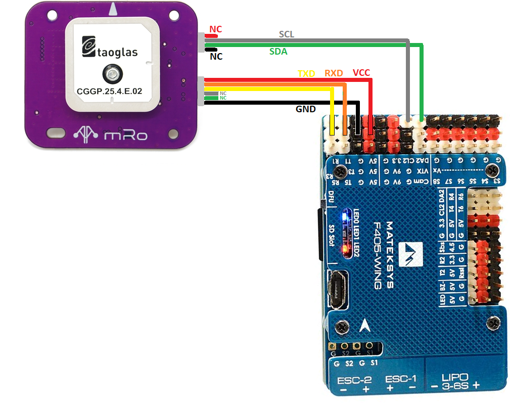
Note
A battery must be plugged in for power to be provided to the 5V pins supplying the GPS/compass modules.
Firmware
Firmware for this board can be found here in sub-folders labeled “MatekF405-Wing”.