CORVON743V2
The CORVON743V2 is a flight controller designed and produced by CORVON, built around the STM32H743 with 10 motor outputs and 2 servo outputs.
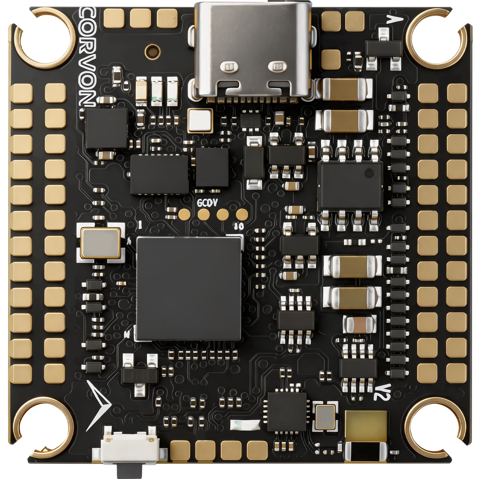
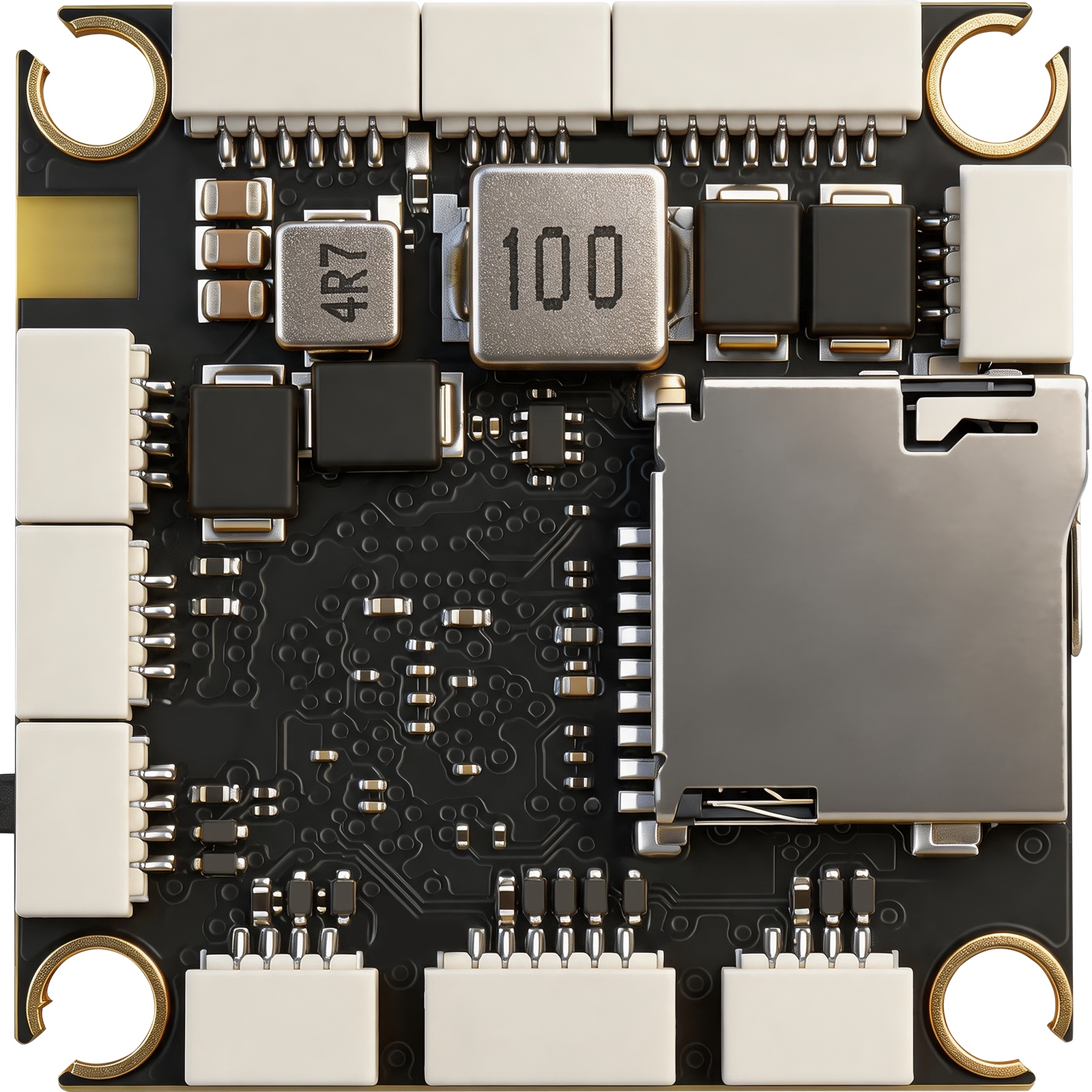
Features
STM32H743VIH6 microcontroller (Cortex-M7 @ 480 MHz, 2 MB flash, 1 MB RAM)
ICM-42688P and BMI088 IMUs
BMP581 barometer
IST8310 magnetometer
10 DShot motor outputs (bidirectional DShot on outputs 1-8) plus 2 PWM servo outputs
8 UARTs plus USB
1 CAN (DroneCAN)
Dual analog battery monitoring
Analog airspeed and RSSI inputs
microSD card slot for logging
Onboard Bluetooth module for telemetry
RGB status LED and WS2812 serial LED output
Passive piezo buzzer
4 user GPIO pads (SW1-SW4)
Mechanical
Mounting: 30.5 x 30.5mm, Φ4mm
Dimensions: 36 x 36 x 8 mm
Weight: 9.1g
Pinouts
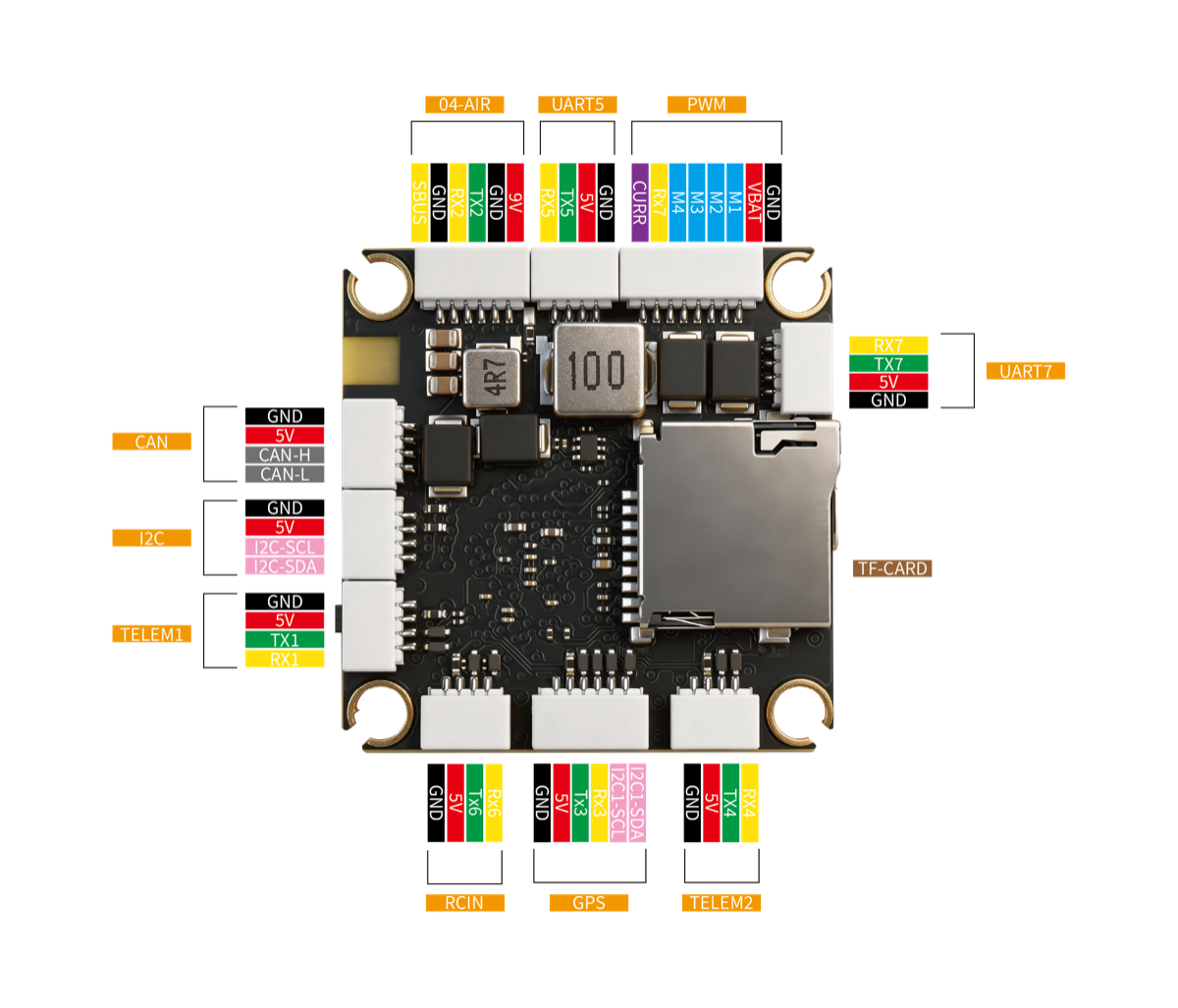
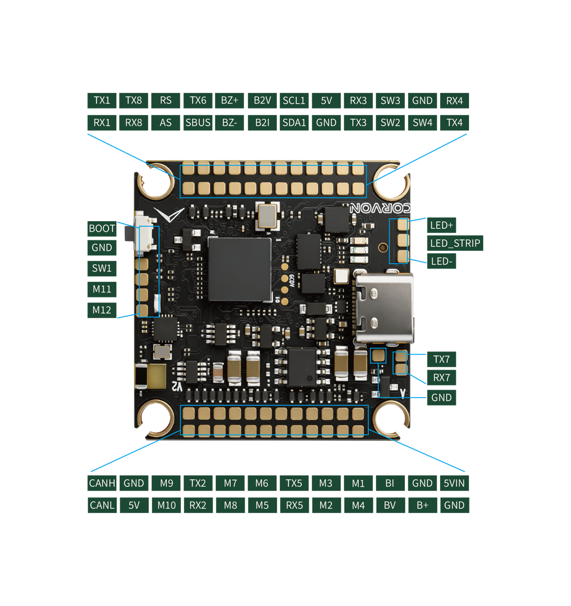
UART Mapping
SERIAL0 -> USB (MAVLink2)
SERIAL1 -> USART1 (MAVLink2, TELEM1 connector)
SERIAL2 -> USART2 (MSP DisplayPort, O4-AIR connector)
SERIAL3 -> USART3 (GPS, GPS connector)
SERIAL4 -> UART4 (MAVLink2, TELEM2 connector)
SERIAL5 -> UART5 (no default protocol, UART5 pads)
SERIAL6 -> USART6 (RC input, RCIN and O4-AIR connectors)
SERIAL7 -> UART7 (ESC telemetry, UART7 pads)
SERIAL8 -> UART8 (MAVLink2 at 115200 baud, onboard Bluetooth)
The O4-AIR connector is a 6-pin header that plugs straight into a DJI O4/O3 Air Unit: USART2 carries the MSP DisplayPort link, its SBUS pin is wired to the RC input on USART6, and the remaining pins supply power and ground.
Bluetooth
The board has an onboard Bluetooth Classic (SPP) module connected to UART8 (SERIAL8), set up for MAVLink2 at 115200 baud by default, so a ground station can connect wirelessly without any configuration.
RC Input
RC input is on the RCIN connector (USART6) with SERIAL6_PROTOCOL set to “23” by default. It supports SBUS, CRSF, ELRS, and other serial RC protocols; bidirectional protocols such as CRSF and ELRS use both the TX and RX pins. The SBUS pin of the O4-AIR connector feeds the same input. See Radio Control Systems for details on each protocol.
OSD Support
The default configuration sets OSD_TYPE = 5 (MSP DisplayPort) on SERIAL2, so a DJI O4/O3 Air Unit connected to the O4-AIR connector shows the OSD overlay without any additional setup. The board has no onboard analog OSD chip, so analog video OSD is not supported.
PWM Output
The CORVON743V2 provides 12 motor/servo outputs plus a serial LED output. All motor outputs support PWM, DShot, and bidirectional DShot on outputs 1-8.
The outputs are grouped and every output in a group must use the same output rate and protocol:
1, 2, 3, 4 are Group 1 (bidirectional DShot capable)
5, 6 are Group 2 (bidirectional DShot capable)
7, 8, 9, 10 are Group 3 (bidirectional DShot capable on 7 and 8)
11, 12 are Group 4 (PWM only, intended for servos)
13 is Group 5 (WS2812 serial LED output, see below)
LEDs
The board has a GPIO-driven RGB status LED used by the ArduPilot notify system.
A WS2812 serial LED (NeoPixel) output is broken out on the LED+ / LED_STRIP / LED- pads: LED+ is 5V, LED_STRIP is the data signal (output 13), and LED- is ground. It is enabled by default, so a strip lights up out of the box; set NTF_LED_LEN to the number of LEDs on the strip.
GPIOs
The motor/servo outputs and the four SW pads can be used as GPIOs (for relays, PINIO, etc.). SW1-SW4 are general purpose user pads, not a dedicated safety switch.
M1-M13 are GPIOs 50-62
SW1-SW4 are GPIOs 70-73
Battery Monitoring
The board has two independent analog battery inputs for voltage and current, on the BV/BI pads (battery 1) and B2V/B2I pads (battery 2).
The default battery parameters are:
BATT_MONITOR = 4
BATT_VOLT_PIN = 10
BATT_CURR_PIN = 11
BATT_VOLT_MULT = 21.12
BATT_AMP_PERVLT = 40.2
BATT2_MONITOR = 4
BATT2_VOLT_PIN = 4
BATT2_CURR_PIN = 8
BATT2_VOLT_MULT = 21.12
BATT2_AMP_PERVLT = 40.2
Both battery monitors are enabled by default; tune the voltage and current scales to match the power modules in use.
Analog Inputs
In addition to the two battery monitors, the board provides:
Analog airspeed input on the AS pad (analog pin 18); set ARSPD_TYPE = 2 to enable
Analog RSSI input on the RS pad (analog pin 3); set RSSI_TYPE = 1 to enable
Compass
The CORVON743V2 has a built-in IST8310 compass. Due to potential interference from the power system, users normally disable it and use an external compass attached to the GPS connector (I2C1), which is auto-detected via ArduPilot’s normal compass probing.
CAN
A single FDCAN interface is exposed on the CAN connector for DroneCAN peripherals.
Loading Firmware
Firmware for this board can be found here in sub-folders labeled “CORVON743V2”.
The board ships with an ArduPilot bootloader, so “*.apj” firmware can be loaded from any ArduPilot ground station. To update the bootloader itself, flash the “with_bl.hex” firmware over DFU (plug in USB with the bootloader button pressed) using your favorite DFU loading tool.