Configuration
The antenna tracker requires much of the same basic configuration as Copter and Plane and then some specific configuration specific to the antenna tracker. Below are the details of this set-up.
Setting the AHRS orientation
If the flight controller board could not be mounted so that its forward direction is aligned with the antenna (as mentioned on the Assembling a frame page) the AHRS_ORIENTATION parameter should be set from the Mission Planner’s Config/Tuning >> Advanced Params screen.
Some commonly used values include:
Pitch90 : the flight controller is pointing up at 90 degrees compared to the direction of the antenna
Pitch270 : the flight controller is pointing down at 90 degrees compared to the direction of the antenna
Accelerometer Calibration
The accelerometer calibration is the same as for Copter meaning the flight controller board should be connected to the Mission planner and then the Initial Setup | Mandatory Hardware | Accel Calibration routine should be run which involves holding the board in 6 separate orientations positions so that offsets and scaling can be calculated.
Setting the Compass orientation
If an external GPS+compass module is being used but the arrow on the case could not be aligned so as to point in the same direction as the antenna, the COMPASS_ORIENTATION parameter should be set.
Some more commonly used values include:
Yaw 90 : the arrow on the compass module is pointing off to the right at a 90 degree angle clockwise from the direction the antenna is pointing.
Yaw 270: the arrow is pointing to the left at 90degrees from the antenna. I.e. the arrow is rotated at 90deg counter-clockwise from where the antenna is pointed.
Compass Calibration
The compass calibration can be done using the same method as Copter. Open the Mission Planner’s Initial Setup >> Mandatory Hardware >> Compass screen and push the “Live Calibration” button and rotate the board until the mission planner says it has captured enough points to correctly calculate the offsets.
Setting the servo and range of movement
For this section it is best to plug in the battery so that the servos are powered and push the “arming switch” if present. Connect with the Mission Planner, go to the CONFIG/TUNING >> Extended Tuning page.
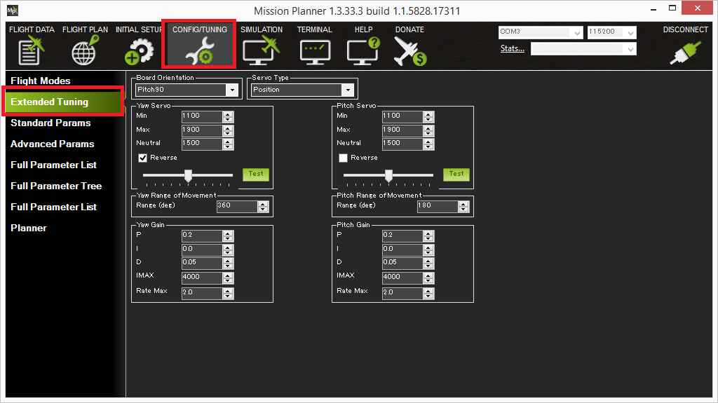
Setting the Yaw servo’s min and max pwm values
The green “Test” buttons on this screen work in conjunction with the Min, Max field values and the slider position. If the slider is pushed all the way to the left and the Test button is pushed, the pwm value in the “Min” field will be sent to the servo. If the slider is pushed all the way to the right and the Test button is pushed, the pwm value in the Max field will be sent to the servo.
If the Yaw (aka pan) servo’s minimum and maximum pwm values are known, they can simply be entered into the Yaw Servo Min and Max fields. If they are not know, you can discover them through experimentation. For example to discover the minimum, push the slider all the way to the left and then enter progressively lower pwm values (pushing the Test button after each change) until you discover the lowest value that causes the servos to move. Repeat for the Max field by pushing the slider all the way to the right and entering progressively higher pwm values.
Normally lower pwm values should cause the tracker to point to the right (i.e. clockwise), higher values will point to the left (i.e. counter-clockwise). If this is not the case, the “Reverse” checkbox should be checked. Note that changing this checkbox will not affect how the tracker operates when using the Test button.
The Neutral field is the value that will be output to the servos when the tracker first begins controlling them after startup.
Setting the Yaw servo’s range of movement
In this step we want to discover the heading change that comes from moving the servos between their minimum and maximum values. One way to do this is to:
Put the slider all the way to the left (if the Reverse checkbox is unchecked) or right (if the Reverse checkbox is checked) and push the Test button
Rotate the tracker so that its heading (on the MP’s Flight Data screen) shows close to “0” (i.e. North)
Return to the extended tuning page, push the slider all the way to the other extreme and push Test
The new heading back on the Flight Data screen is the range of movement and should be entered into the “Range of movement field”.
Setting the Pitch servo’s range of movement pwm values
Repeat the procedures described above to discover the Yaw servo’s min and max values except using the fields and buttons in the “Pitch Servo” section of the Extended Tuning screen.
Lower pwm values should cause the tracker to aim down, higher pwm values to aim up. If this is not the case, the “Reverse” checkbox should be checked.
Setting the Pitch servo’s range of movement
Repeat the procedures used to discover the Yaw servo’s range of movement except that the difference in the Pitch values shown on the Mission Planner’s Flight Data screen should be used.
Manually setting the parameters
If the mission planner is not being used the parameters below can be updated manually:
RC1_ parameters control the pan (aka yaw) servo
RC1_MIN : min pwm value that can be sent to the pan servo
RC1_MAX : max pwm value that can be sent to the pan servo
RC1_REV : set to “-1” if the tracker rotates in the wrong direction
RC2_ parameters control the tilt (aka pitch) servo
RC2_MIN : min pwm value that can be sent to the tilt servo
RC2_MAX : max pwm value that can be sent to the tilt servo
RC2_REV : set to “-1” if the tracker tilts in the wrong direction (i.e. tilts down when vehicle is above tracker)
Tip
For continuous rotation set YAW_RANGE equal to 360. Make sure you hardware setup (i.e. the cabling) can handle the tracker turning continuous circles.
Tuning
YAW2SRV_P, I and D values are set the pan control’s gains.
PITCH2SRV_P, I and D values are set the tilt control’s gains.