Vibration Damping
Autopilots have accelerometers that are sensitive to vibrations. These accelerometer values are combined with barometer and GPS data to estimate the vehicle’s position. With excessive vibrations, the estimate can be thrown off and lead to very bad performance in modes that rely on accurate positioning (e.g. on Copter: AltHold, Loiter, RTL, Guided, Position and Auto flight modes).
Please refer to the Measuring Vibration page for details of how to measure your vehicle’s vibration levels and confirm they are within the acceptable range
The goal of vibration damping is to reduce high and medium frequency vibrations while still allowing low frequency actual board movement to take place in concert with the airframe.
Double sided foam tape or Velcro has traditionally been used to attach the autopilot to the frame. In many cases foam tape or Velcro does not provide adequate vibration isolation because the mass of the autopilot is so small.
Note
The examples and images in this article refer to Copter, but the information is also largely applicable to Plane and Rover.
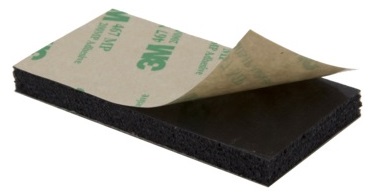
3M, Du-Bro or HobbyKing Foam
One of the following three types of foam should be cut into small 1cm ~ 2cm squares and attached to each of the four corners of the autopilot as described on the Mounting the Autopilot wiki page:
- 3M Foam is sticky on both sides and comes pre-cut so that individual squares can be easily attached to the autopilot
HobbyKing orange foam (discontinued)
For the last two options “carpet fixing tape” will be required to attach the foam to the autopilot and vehicle frame.
For vehicles with internal combustion engines, the autopilot should be mounted on an intermediate plate with self adhesive lead weights added to increase its mass.
Gel pads
Cut one of the recommended gels into 1cm ~ 2cm squares and attach to each corner of the autopilot. Possible gels include:
Kyosho Zeal Gel Tape performs best and is available from Amazon, E-Bay and A-Main Hobbies
United States Silicone Gel Tape and Pads (V10Z62MGT5 tape recommended)
Moon Gel Pads (also available in music stores). Caution: Moon Gel has been shown to fail in heat above 100 degrees Fahrenheit so it should be used cautiously.
Secure the autopilot to the frame with 1cm) wide velcro retaining strap or a rubber band. Be careful the strap does not hold down the controller so securely that it interferes with the damping of the pads. Consider putting a layer of soft foam between the strap and the autopilot.
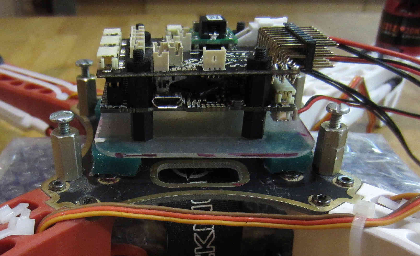
FlameWheel F330 with PX4FMU Mounted on Intermediate platform
The blog Testing simple anti-vibration solutions for GoPro on an ArduCopter has a video demonstrating vibration isolation using Moon Gel on a Go-Pro camera.
3D Printed Anti-Vibration Platform
GuyMcCaldin’s 3D Printed vibration mount on Thingiverse using dampers like these.
The mount can be installed using double sided tape, or M3 screws.
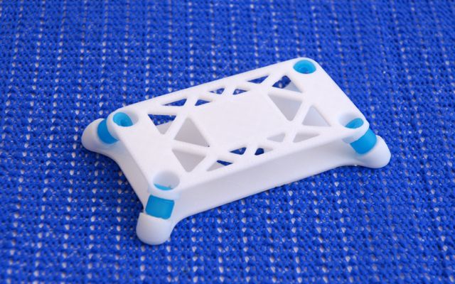
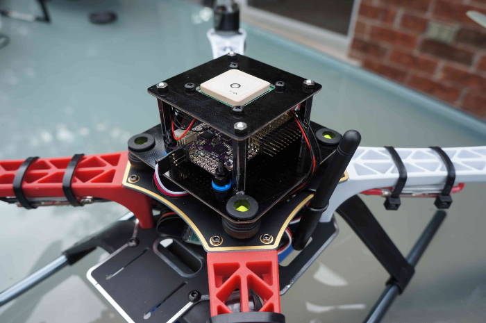
3D Printed Anti-Vibration Platform for NAVIO2
Anti-vibration for NAVIO2 can be easily 3D printed. It significantly simplifies mounting and eliminates vibrations. You can find STL files here.
Anti-vibration with Navio2 mounted on frame:

O-ring Suspension Mount
Create a platform upon which to mount your autopilot with holes or screws on the four corners. Mount your autopilot on this board with double sided foam tape.
Mount 4 standoffs on the top of your frame spaced 1/10” to 1/8” further apart than the width of the platform upon which the control board has been mounted.
Insert 1/16” nylon O-rings through each corner of the autopilot and the standoffs so that the autopilot has no hard connections to the frame. Link (Here!)
The overall O-ring diameter should be chosen to firmly retain the board while providing for light to moderate initial but rapidly snubbed movement of the board (generally 1/2” to 3/4” OD) and Silicone O-rings should generally damp better than Buna-N O-rings (Sizes 15 - 21) if you can acquire them.
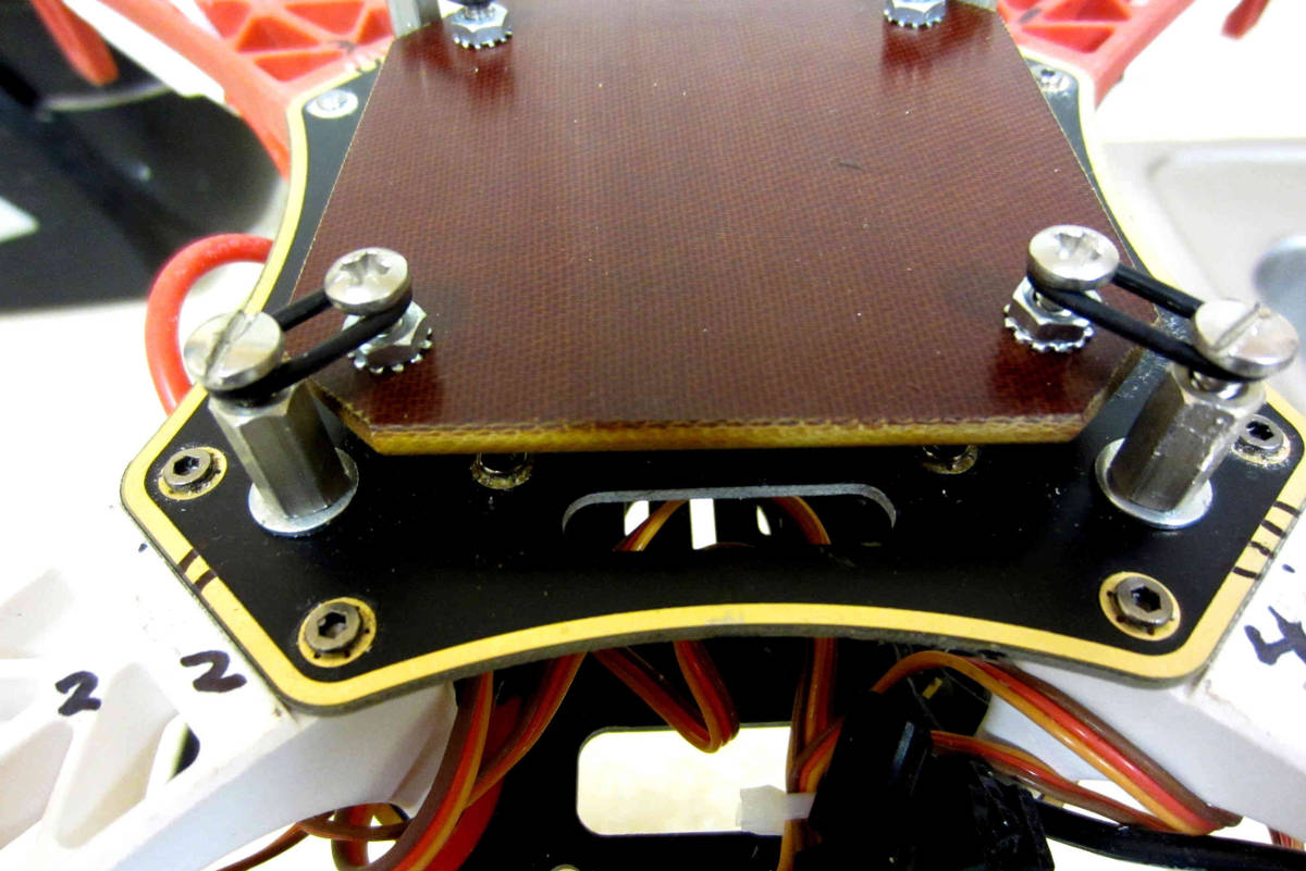
FlameWheel F450 O-Ring Suspension Platform Mount
Vibrations are short coupled, so all that leaving excess corner clearance does is to require higher initial O-ring tension which reduces vibration damping responsiveness and allows the board to physically tilt more (which is undesirable as it throws the sensor to airframe relationship off).
The disadvantage to O-ring suspension versus Gel pads is that it is mechanically more complex and it requires tuning of both of O-ring diameter and cross section.
You can combine O-ring and gel pad design by using an intermediate plate and benefit from dual rate damping.
Ear Plug Mount
Purchase slow response silicon or urethane foam or PVC foam earplugs such as these from 3M.
Create a platform upon which to mount your autopilot with holes at the four corners. The holes should be large enough to allow the ear plugs to be inserted into them but not so loose that the board comes loose during hard landings. Ensure the holes are smooth so they do not cut into the ear plugs. Also keep the holes near the corners of your electronic module plate as possible to minimize unnecessary module movement.
Mount your autopilot on this board with double sided foam tape. Extra mass added to the board may improve vibration damping.
Squeeze the earplugs through existing holes in the frame (or cut new holes) and the holes in the board upon which the autopilot is mounted. “Tuning” is possible by varying the amount of earplug left exposed in the middle.
Ear Plug Vibration Mount
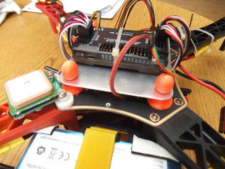
Bulb Damper + Ear Plug Vibration Mount
Mounting plate with a 100g soft rubber bulb type “gimbal” damper at each corner and a half a urethane foam earplug placed inside each one.
Gimbal bulb type dampers themselves can work in tension or compression.
The earplugs provide an additional damping medium with a different frequency damping range than the bulb dampers by themselves.
The ear plugs also stiffen the bulb mounts up a bit preventing excessive free motion being caused by normal flight maneuvers.
This was successful at damping a Flamewheel clone with flexible arms and over size 12” propellers into the .05 G range.
The autopilot is also mounted on anti-vibration grommets available from McMaster Carr (package of 25 each part #9311K64 recommended).
The 100G bulb type gimbal vibration dampers can be ordered direct from a variety of vendors: copter-rc.com
Advice for reducing vibrations
For copters the largest source of vibration is normally the blades passing over the arms but other sources of vibration also exist and may be reduced by following this advice:
Frame flex especially arm flex is a big cause of asynchronous vibration, Frame arms should be as rigid as possible.
Original DJI Flamewheel copters have sufficiently rigid injection molded arms, the many clones do not
Aluminum or carbon fibre arms twist and bend less which reduces vibrations
Copters with injection molded exoskeletons or arms like the Iris are sufficiently rigid
Cheap, light frames tend to flex more than high quality stronger ones and the heavier you load the copter the more flex it gets (not good)
Motor to frame arm and frame arm to central hub mounts need to be secure and flex free (sometimes a problem for carbon tube arms)
Motors need to run smoothly (bearings not worn-out or “screeching”)
Prop adapters connecting the propellers to the motors need to be concentric and very straight
Propellers should be fully balanced using a good manual prop balancer
Motor balancing (or really well factory balanced motors like T-Motor) can have a major effect
Propellers that are not well matched to the frame and weight or do not have the same flex for CCW and CW are very problematic
Good propellers vibrate less
Carbon fiber props are rigid and vibrate less which reduces vibration but are very sharp which is a major safety hazard
Summary of the vibrations that should be damped
The vibration frequency and amplitude we primarily need to reduce is a characteristic of the motor / prop units turning at flight speed.
That is, it is a fairly high frequency with fairly low amplitude.
This requires that we provide a short coupled damping and isolation range.
The board itself does not need to have nor benefit from a range of motion that exceeds the amplitude of the vibration.
Because the board does not apply any force to the airframe, the only thing we need to be concerned with Damping / Isolating is the weight (mass) of the board itself plus the forces applied to it by airframe’s normal flight maneuvering.
Since excellent broad frequency range, high damping materials are available our biggest concern will be to use the proper amount of them to optimally damp our autopilot (too much is just as bad as too little).
Combining the autopilot and receiver onto a separate vibration damped electronics module “plate” or enclosure can increase the mass of the module making it easier to damp effectively as well as reducing the interconnecting wiring and making the whole system more modular.
Additional Vibration Reduction Considerations
Hard Disk Drive Anti-Vibration Grommets. can provide sufficient or supplemental vibration reduction
Significant gains in vibration isolation can also be realized by using a high flex wire and strain relief approach to all wires connected to the autopilot (and using the minimum number of wires necessary as well).
Some frames have lower than normal vibration characteristics due to frame stiffness / flex and isolated centralized mass can greatly influence motor/prop vibration transfer to the central fight controller.
Isolation and damping can be improved somewhat by sandwiching the autopilot / enclosure between damping pads on both sides in about twenty percent compression. 30 durometer Sorbothane is actually specified at 15 to 20 percent compression for optimal damping.
Although 30 durometer Sorbothane seems an excellent candidate, experience indicates that it becomes permanently compressed and is not as effective at vibration reduction as the Gel solutions.
A link to a Blog about the first APM anti-vibration mounting system to achieve 0.05 G damping (2/20/2013 improved to 0.02 G), a dual zone isolation system, combining O-ring suspension and silicone pad is (Here!)
Motor balancing can also reduce vibration and especially so for cheaper or larger motors. Balancing involves:
Tightly fasten a small tie wrap around a motor (WITH NO PROP), trim off the extended tab and spin it up.
Try multiple times, each time turning the tie wrap on the motor housing a bit until the vibration reduces or goes away.
A small piece of Scotch tape can be re-positioned instead of the tie wrap if desired or for smaller motors.
When you locate the spot where there is the least vibration (and you should be able to hear it), mark the spot directly under the clasp of the tie-wrap with a felt pen.
Add a small dot of hot glue gun glue where the Tie-Wrap clasp was and increase the glue a bit at a time till the vibration is minimized.
If you put too much glue on it can be removed with an X-acto knife.
Camera Mounts also need to be effectively isolated and damped from vibration, but they already have a number of “soft” mounting solutions.
The camera servos need to be vibration isolated as well, either in the isolated camera mount itself or with their own vibration reduction solution.
You should use high quality ball joints on your camera servo arms and adequate bearings or bushings in the mount itself with zero free play to prevent inertial slop.
Quality servos without free play are also a must for precision camera work.
At this point in time it seems that the more rigid the frame the better because frame flex introduces undesirable mechanical delay (hysteresis) in translating motor induced actions to the centrally located autopilot. (Do NOT shock mount the motor Arms).
The amount and type of damping medium needs to be carefully matched to the weight (mass) of the item we are trying to isolate as well as the frequency and amplitude of the vibrations we are seeking to damp. We are trying to isolate an autopilot that weighs less than 2 ounces and this is a very small mass.
Virtually all off the shelf solutions (either pad or stud type) are designed for an isolated mass that would weigh at least 5 to 10 times what an average autopilot weighs for optimal effectiveness. This includes all pre-made Sorbothane, Alpha gel, EAR, memory foam or other silicone or urethane gel or foam mounts as well as Lord Micro mounts.
A threaded stud or sleeve type mount gel mount properly designed for the mass of our autopilot or electronics module undergoing the stress’s of normal flight would be a much better long term solution.
Terminology
The methods used will typically incorporate both damping and isolation:
Isolation is simple undamped (spring or rubber band support) which allows the movement of the isolated object largely separate from the containing object (Automobile spring for instance).
Damping is the conversion of vibration into heat energy by a shock absorbing medium (automobile shock absorber for instance).