DroneCAN ESCs
Copter, Plane and Rover support DroneCAN Electronic Speed Controllers (ESCs) that allow two-way communication with the autopilot enabling potentially easier setup and in-flight monitoring of ESC and motor health.
List of DroneCAN ESCs
Connecting to the Flight Controller
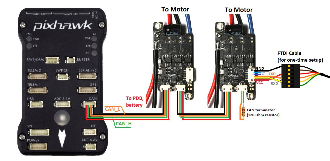
One ESC (it does not matter which) should be connected to the autopilot’s CAN port using a 4-pin DF13 to 4-pin DroneCAN adapter cable. Each subsequent ESC should be connected to the previous using a 4-pin DroneCAN cable. The final ESC should have a CAN bus terminator plugged into one of its 4-pin DroneCAN ports.
An FTDI Cable connection to the ESC’s debug port is only required for set-up if the ESC does not present its parameters via DroneCAN. In that case, contact the manufacturer for detailed instructions.
Preferably, the ESC can be configured via CAN bus using the DroneCAN GUI Tool.
Autopilot Setup
There are several parameters that determine which autopilot servo/motor channels are sent to the DroneCAN ESCs: For the examples below, the values are shown for DroneCAN driver #1 using CAN Port #1
CAN_P1_DRIVER = 1, which assigns driver1 to port1
CAN_D1_PROTOCOL = 1 (DroneCAN protocol)
CAN_D1_UC_NODE - which is the node ID of the autopilot sending the commands to the ESCs so that there can be differentiation between multiple sources on the CAN bus. This is normally automatically set during discovery, but can be altered for advanced configurations (multiple sources on the bus).
CAN_D1_UC_ESC_BM - bitmask that determines which autopilot servo/motor output signals are sent to the DroneCAN ESCSs
CAN_D1_UC_ESC_RM - bitmask that designates which autopilot servo/motor outputs have reversible DroneCAN ESCs, allowing both positive and negative control values to be sent.
Logging and Reporting
DroneCAN ESCs provide information back to the autopilot which is recorded in the autopilot’s onboard log’s CESC messages and can be viewed in any ArduPilot compatible log viewer. This information includes:
Error Count
Voltage
Current
Temperature
RPM
Power (as a percentage)
The RCOU messages are also written to the onboard logs which hold the requested output level sent to the ESCs expressed as a number from 1000 (meaning stopped) to 2000 (meaning full output).
Additional information
Zubax Sapog wiki page, Sapog reference manual, and ESC firmware.